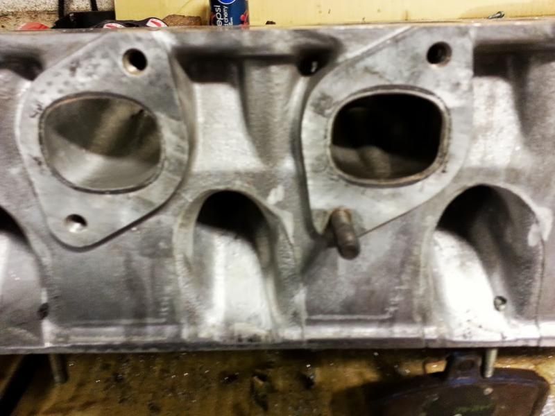
Turbo m30b35 head porting.
So i'm slowly building an m30b35 turbo motor. The intake has been gasket matched, and the exhaust is a tubular style going to a twin scroll twin wastegated hx40. I don't have porting experience, but I have been reading good sources and have a spare head incase I mess my test one. I don't mind posting the information, but i'd love to hear some opinions of something to try next, and I would be willing to put in the man work to see the results from it. I will try to use pictures, if you guys have input or more exp than me let me know.
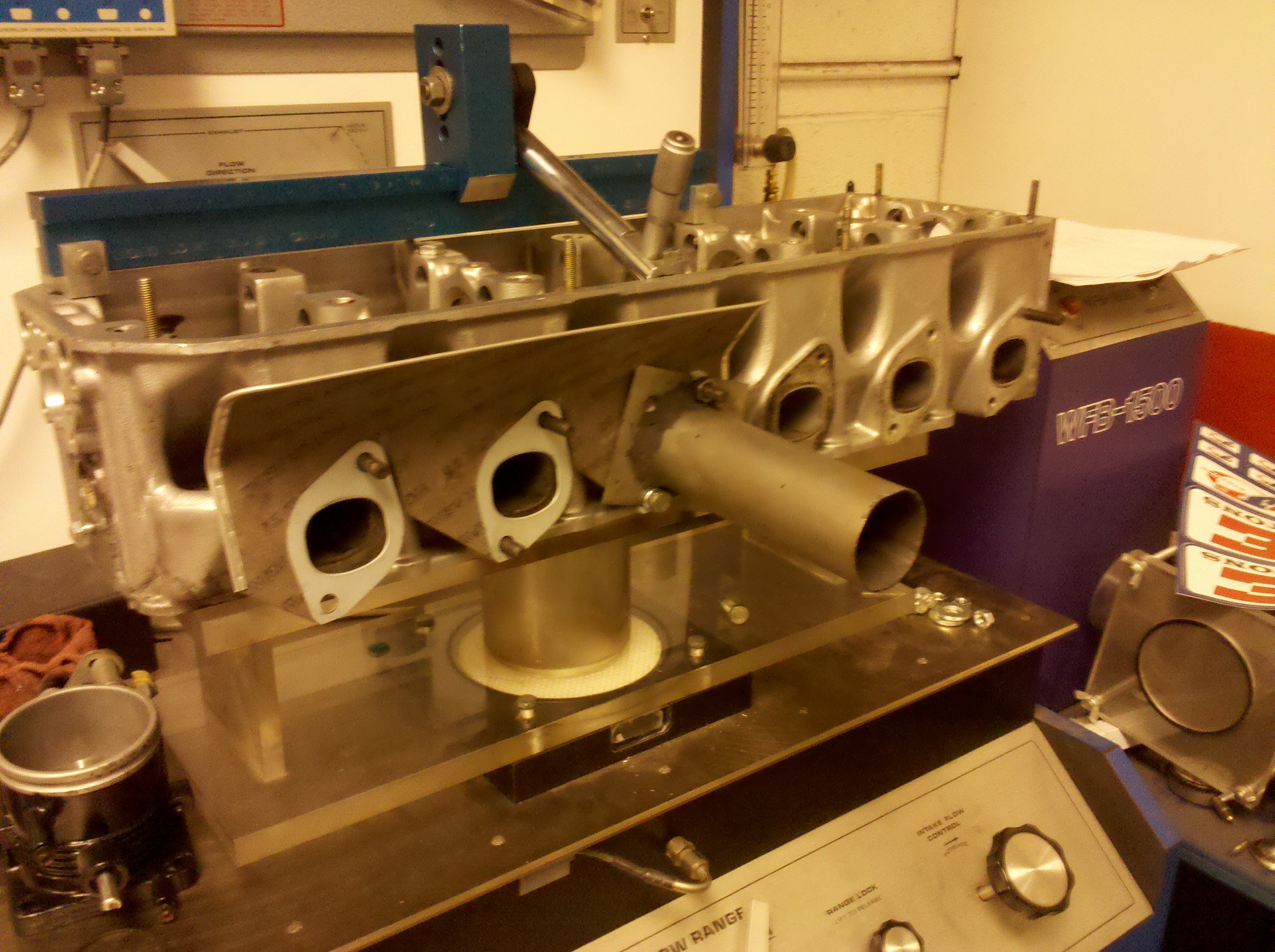
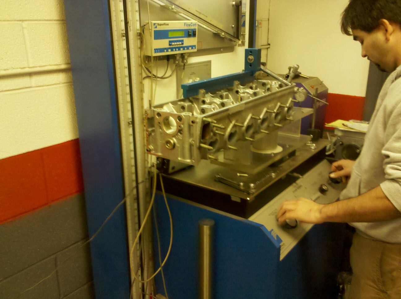
I did the flowbench testing on a bone stock m30b35 head. The vales were bead blasted, and the head was marted (industrial head cleaner).
I did a preliminary valve leakage, which is usually 0-5cfm or so to be calculated from the total CFM. However for whatever reason mine apparently has 0 leakage, which is interesting since its a 200k+ motor from a junkyard but alright. Here are the results, I put the <.5 lift because i'm unable to achieve this do to the spring retainer bottoming on the valve guide seal. Measurements were made at 28" on flow range 4, using a sf-600 flowbench.
stock-m30b35-flowbench.xlsx
Here is my buddy giving me a hand.
-
- Posts: 6859
- Joined: Oct 10, 2008 1:48 PM
- Location: Back U.P. North,. Where the water's blue, the wind is free and seasons four.
I have to disagree with this statement. In the stock configuration the sweet spot of the flow curve falls closer to the .300 measurement than the .400 measurement. There are other concerns for a stock engine than maximum power via lift. Higher lifts mean higher pressures, stronger springs, accelerated cam wear and more rocker arm problems.Lurker27 wrote:And that's why we get cams for these hideously underlifted engines
In a FI engine duration offers more return than lift, right up to the point of losing incoming charge of course.
I'm looking forward to seeing the flow numbers the OP achieves with porting.
Lift past about 10mm doesn't produce much in terms of flow. Higher lift also means higher stress on the valvetrain, so you get shorter rocker arm life and faster wear.
You won't find a whole lot of really good info about port work. That knowledge doesn't come cheap. I've had limited success knowing nothing about what I'm doing. If you've got a flowbench thats a great tool to make effective modifications. If I were you I would start very small with minor tweaks to see what the port likes. Look at some pics of S54 or S85 heads to see what a more ideal port/valve arrangement looks like.
I think these heads would benefit from a steeper intake port with a more vertical shot at the back of the intake valve. Seems like raising the roof of the port near the valve stem could improve flow.
-
- Beamter
- Posts: 23035
- Joined: Apr 08, 2009 10:30 PM
- Location: Charlottesville, VA
- Contact:
Brody from miller performance showed me this chart, as a goal.
https://millerperformancecars.com/files ... 0Chart.pdf
It's also about the project for me.
https://millerperformancecars.com/files ... 0Chart.pdf
It's also about the project for me.
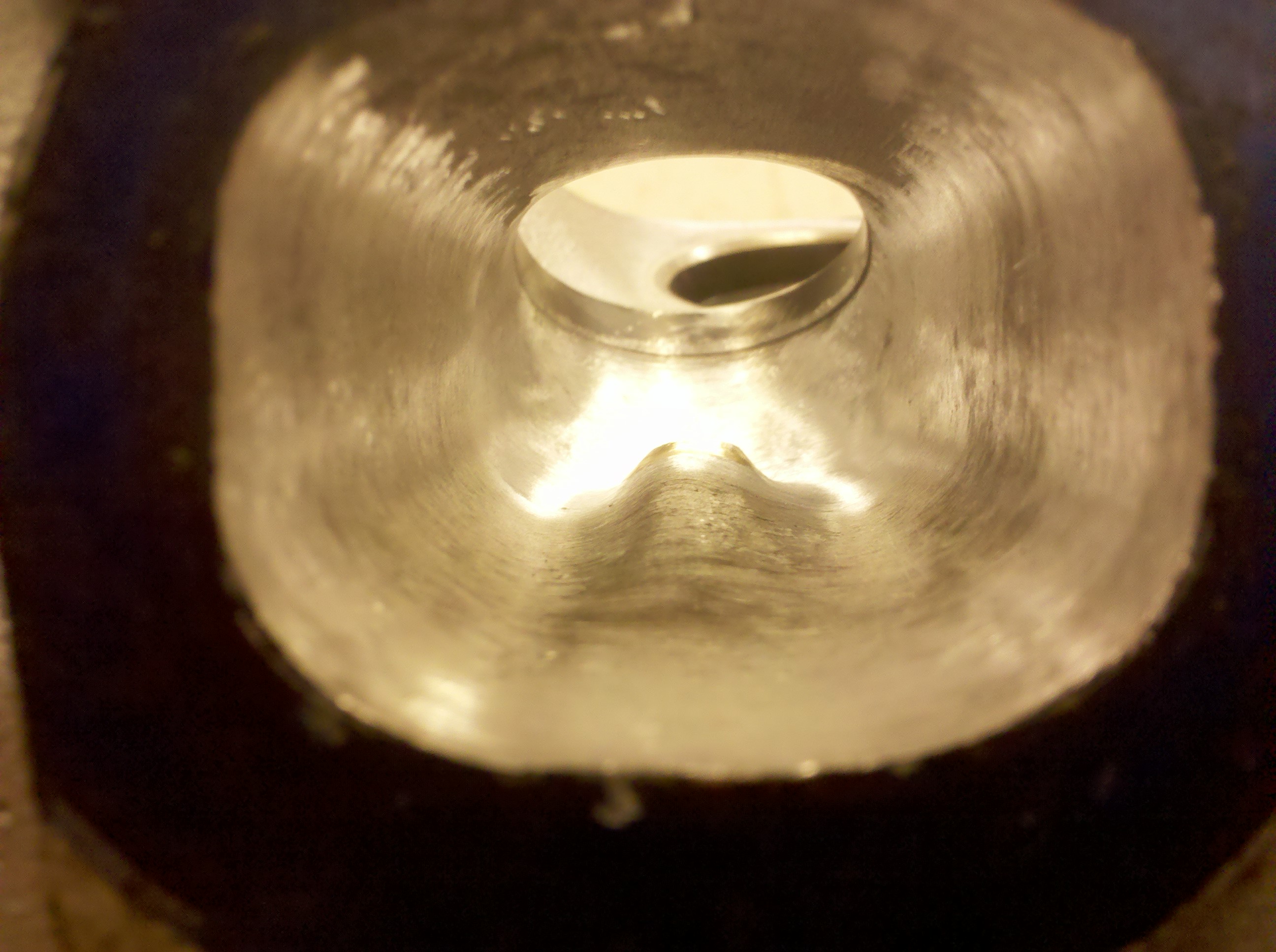
So here is the first actual change, it was a very small change and I expected almost no difference in cfm. Notice how it looks much smoother and stuff, but it still had no affect on cfm. I think a lot of people gasket match, and just smooth things out, and without a bench they are doing either next to nothing or possibly making it worse. At any rate here we are.
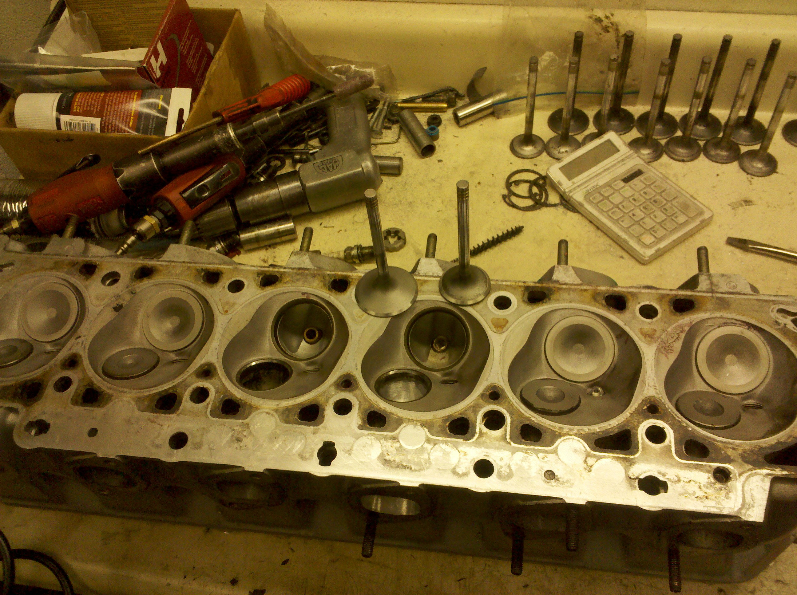
Here we are on the shop bench with some various tools laying around.
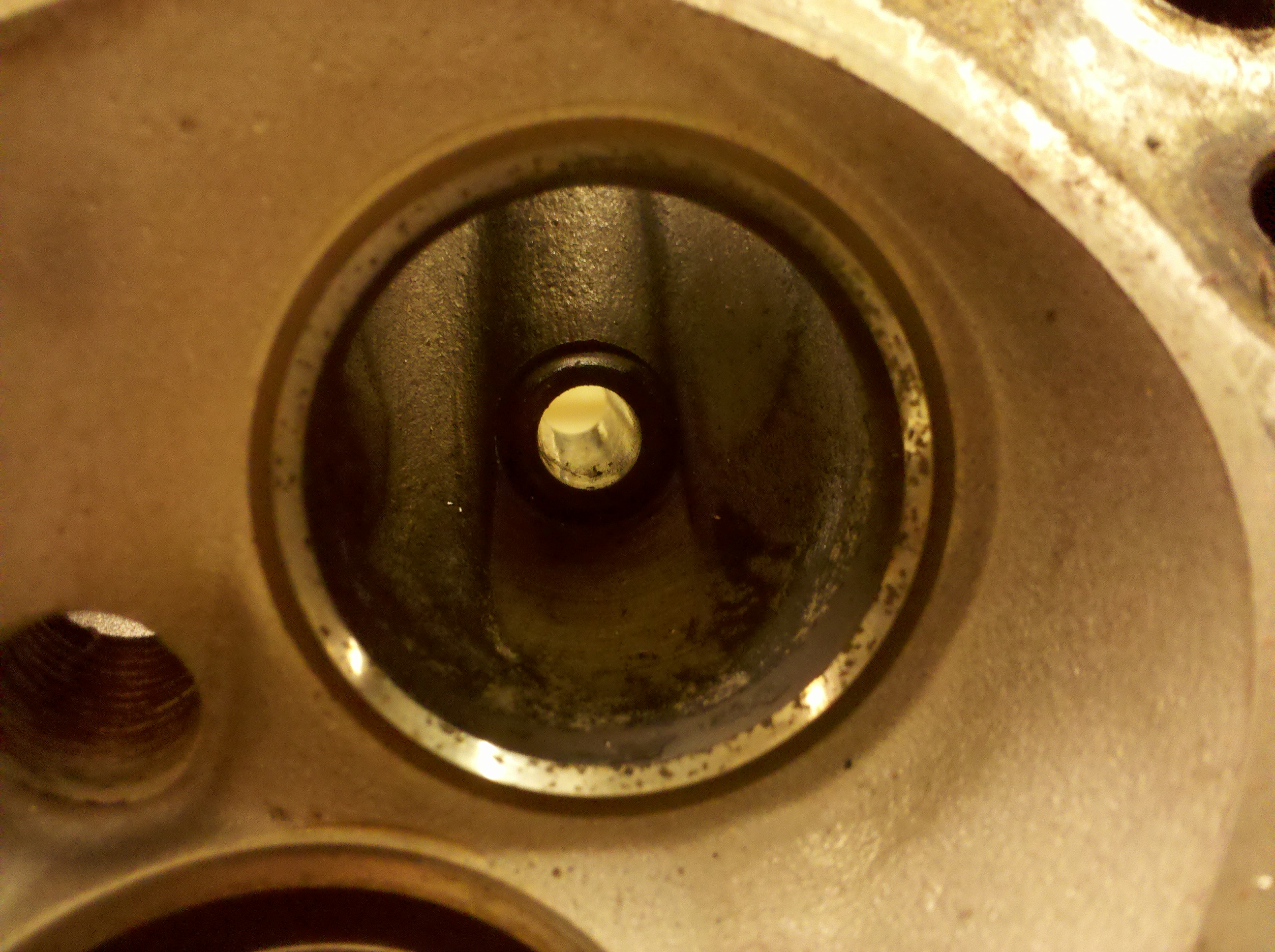
Here is the stock untouched exhaust port for exhaust cyl #4
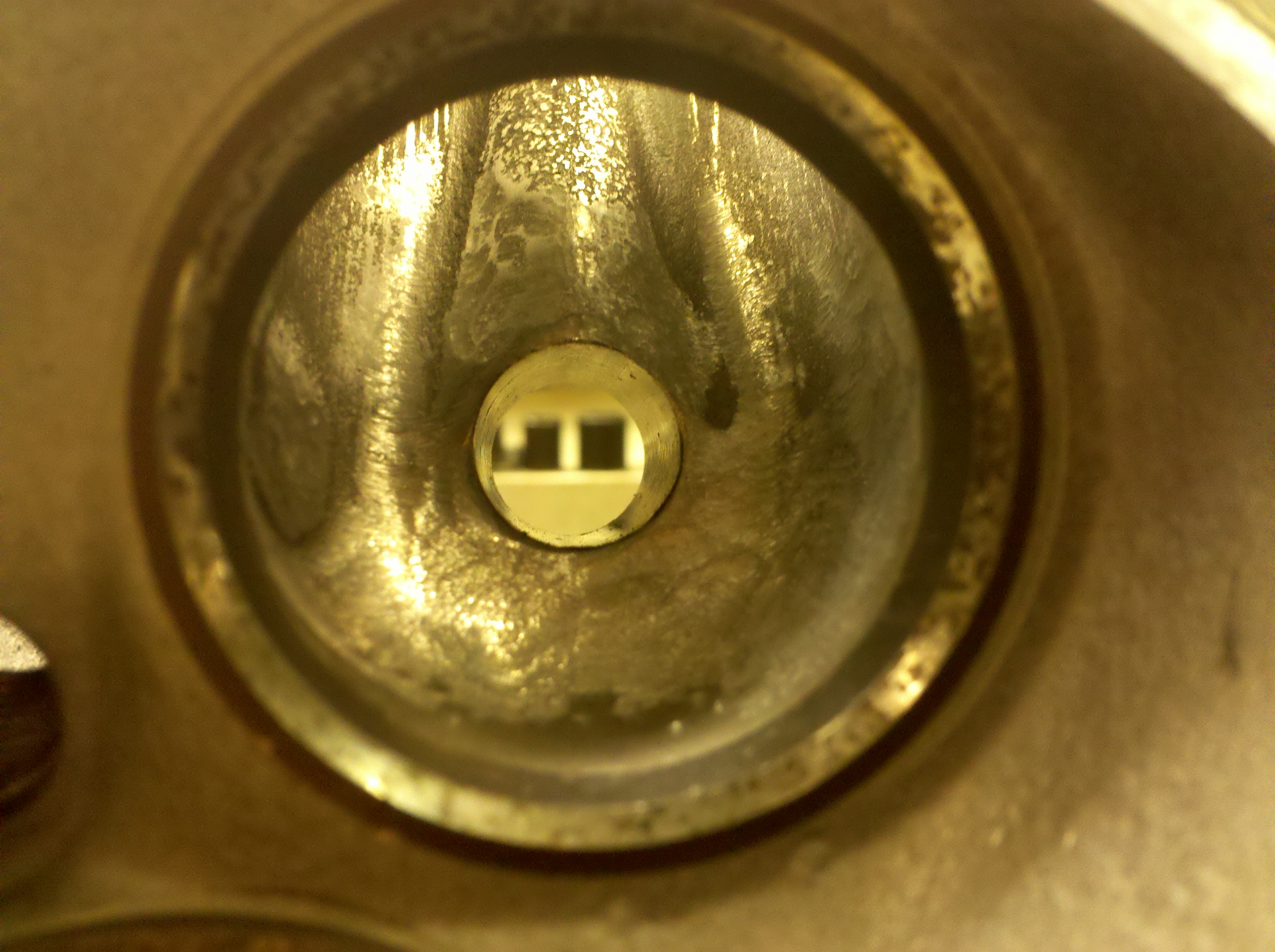
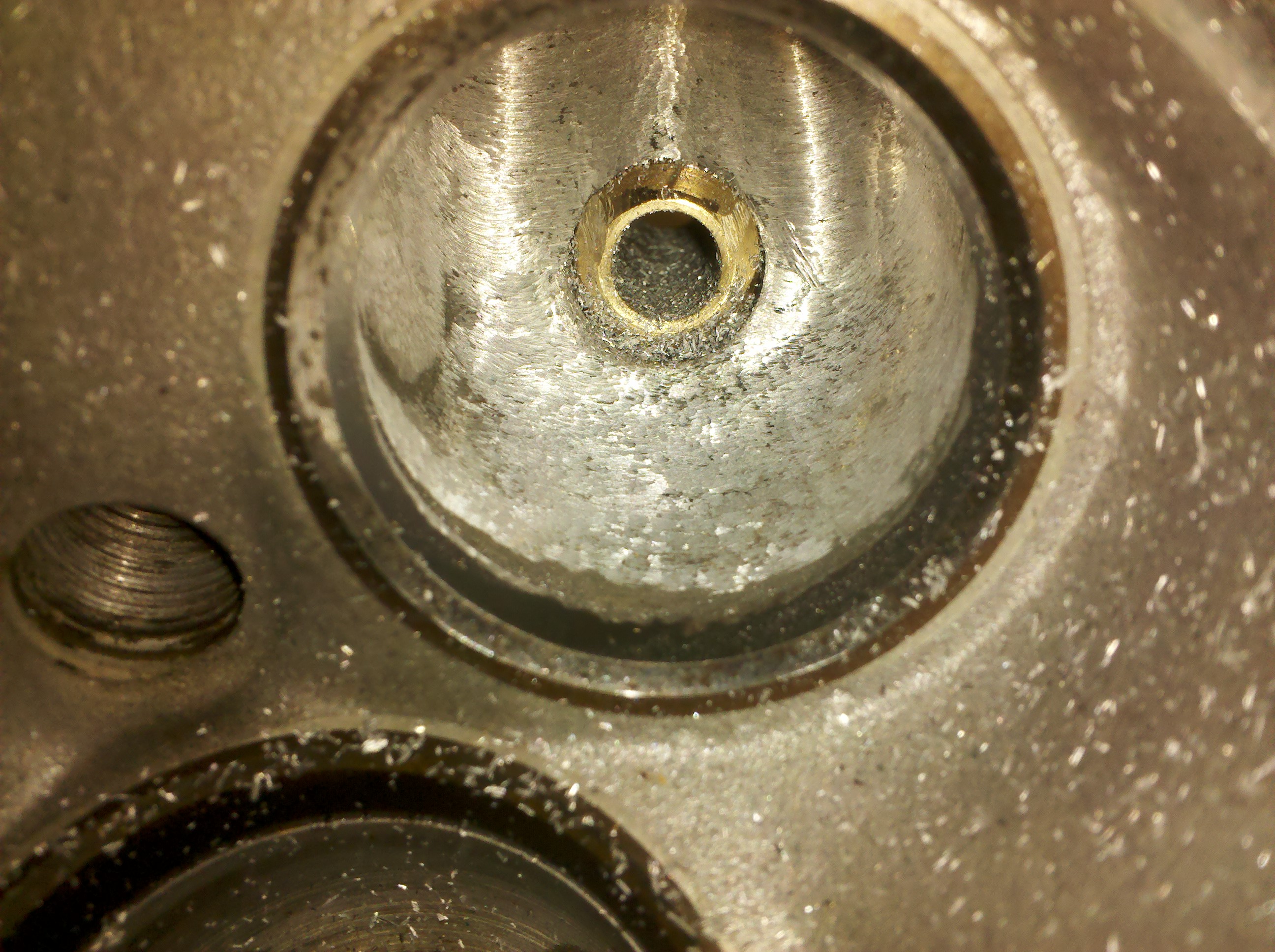
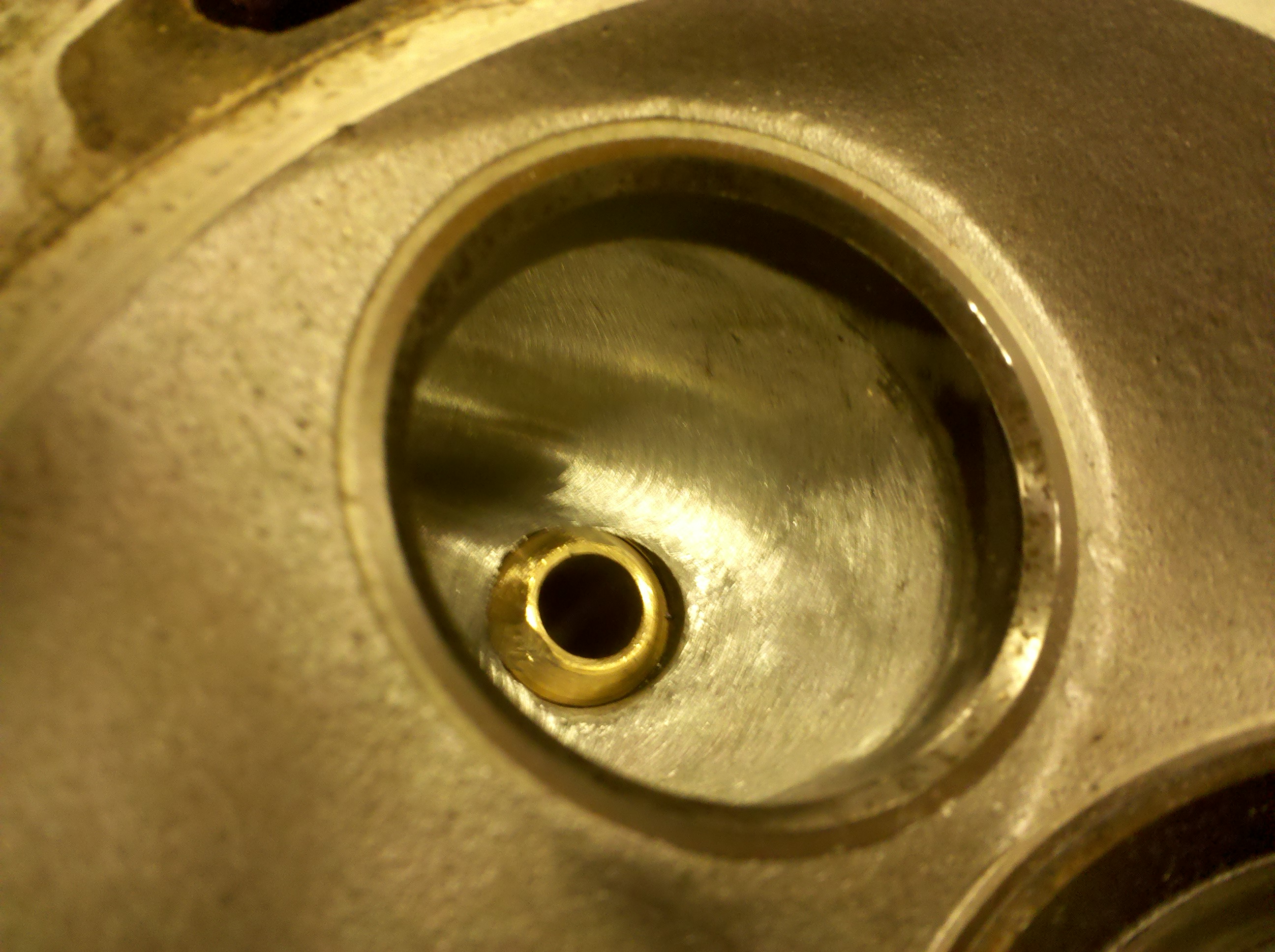
The valve guide was pressed out of the head, and some smoothing around it was done as shown.
The valve guide was cut to match the material that was removed. I don't think cutting the exhaust is necessary, and the difference it made was nothing, it's not worth the effort. The intake may or may not be a different story.
Results are as shown:
Stock exhaust vs slightly modified area around valve guide and cut valve guide. ( Did very small changes to the cylinder head to begin with)
STOCK
.1" 45cfm
.2" 91cfm
.3" 127cfm
.4" 144cfm
<.5" 151cfm
Modified
.1" 43cfm
.2" 89cfm
.3" 128cfm
.4" 145cfm
.5" 154cfm
-
- Beamter
- Posts: 23035
- Joined: Apr 08, 2009 10:30 PM
- Location: Charlottesville, VA
- Contact:
Oh no hold our horses now. The exhaust has much improvement to be had! I don't see any of this is a waste of time. I'm not only personally learning but I am figuring out what works on these heads. I don't see any testing on equipment like this a waste of time. I learn every-time I do something, and to me that's what it's really about. I read a lot of jibberish on port work for these motors, but I have yet to find something solid like real flowbench work, and post difference of each modification. If you do have something like that please show me so i can see what they have done as well. I understood from the beginning on the exhaust side you probably won't gain much, these heads aren't that bad from the git-go. The point is how much more can I squeeze out of them, using tricks i'm sure most people on here haven't even heard of.
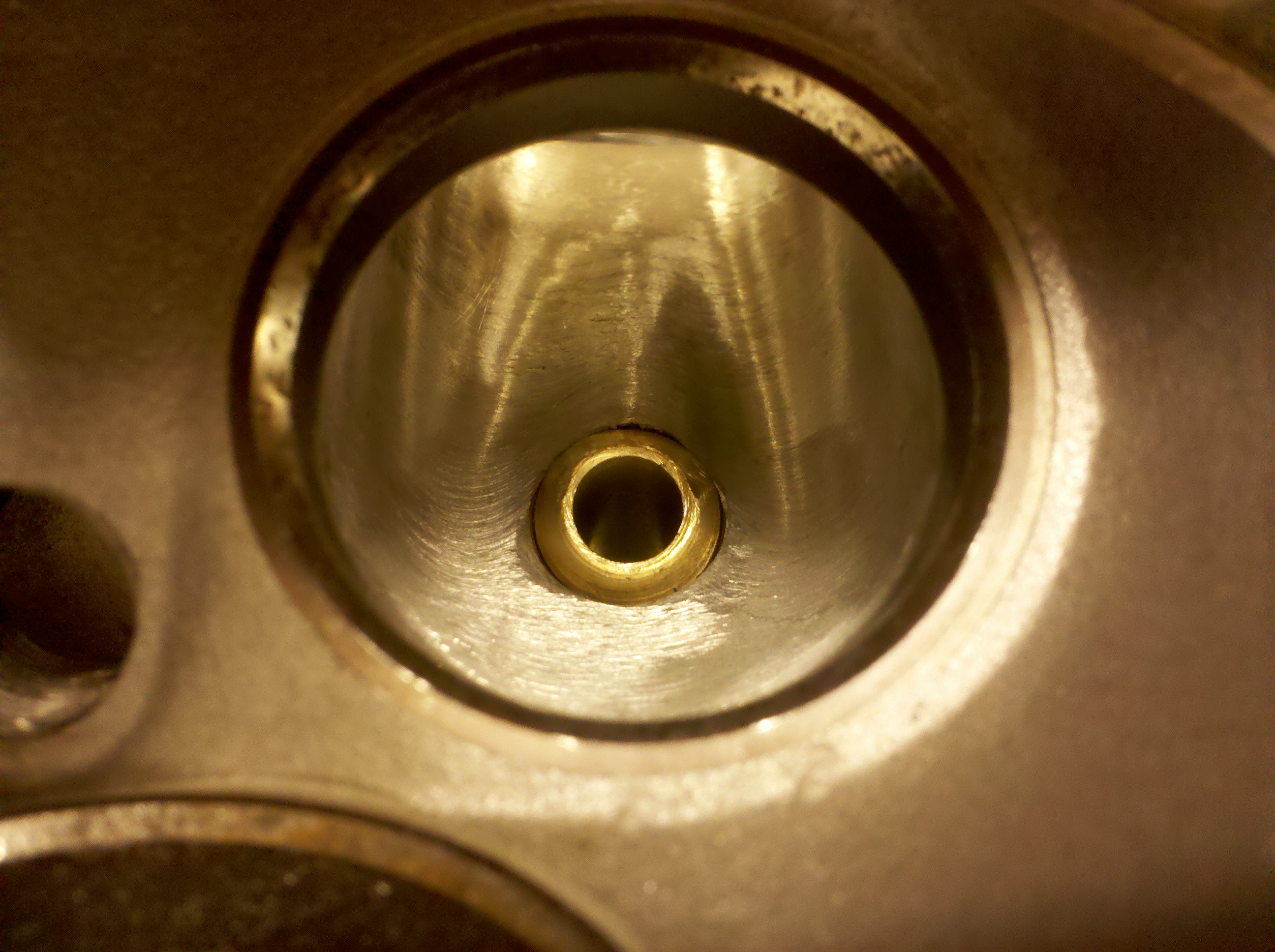
I did some work on 12/15/12 as well on the exhaust. I'm far from doing one stab at the exhaust and calling it a day. I woudn't suggest gasket matching on these engines. I wouldn't want any material removed from the floor, I want it all removed from the roof. To increase the radius of the bend after the valve. I blue dyed the face of the cylinder head, and scribed the gasket mark. I raised the roof of #4 exhaust port up to the scribed line, and haven't touched the sides or the floor of the cylinder. This is step 2 in my exhaust port work, this attempt has a little bit more material removed than the first but nothing crazy. The gains are getting there, nothing absurd yet, but I have a few more tricks up my sleeve, before I say i'm done with the exhaust side.
The next step will be making a pipe to extent from the head, to possibly give me a better reading. This way I can better compare the exhaust readings to the exhaust, for the fact that during testing you radius the intake port with clay. Well many experieneced bench tests suggest the use or a pipe around 6 inches in length to extend from the exhaust port for a more realistic reading.
After that I plan to do valve work, hopefully both a valve job on the head. Which you can't do much there isn't much material to play with. Than after the main cut on the valve, Instead of the sharp edge on the end of the intake and exhaust valves. I'm going to lathe them so the end is radiused around.
STOCK
.1" 45cfm
.2" 91cfm
.3" 127cfm
.4" 144cfm
<.5" 151cfm
Modified 12/15/12
.1" 45cfm
.2" 91cfm
.3" 129cfm
.4" 149cfm
<.5" 158cfm
I did some work on 12/15/12 as well on the exhaust. I'm far from doing one stab at the exhaust and calling it a day. I woudn't suggest gasket matching on these engines. I wouldn't want any material removed from the floor, I want it all removed from the roof. To increase the radius of the bend after the valve. I blue dyed the face of the cylinder head, and scribed the gasket mark. I raised the roof of #4 exhaust port up to the scribed line, and haven't touched the sides or the floor of the cylinder. This is step 2 in my exhaust port work, this attempt has a little bit more material removed than the first but nothing crazy. The gains are getting there, nothing absurd yet, but I have a few more tricks up my sleeve, before I say i'm done with the exhaust side.
The next step will be making a pipe to extent from the head, to possibly give me a better reading. This way I can better compare the exhaust readings to the exhaust, for the fact that during testing you radius the intake port with clay. Well many experieneced bench tests suggest the use or a pipe around 6 inches in length to extend from the exhaust port for a more realistic reading.
After that I plan to do valve work, hopefully both a valve job on the head. Which you can't do much there isn't much material to play with. Than after the main cut on the valve, Instead of the sharp edge on the end of the intake and exhaust valves. I'm going to lathe them so the end is radiused around.
STOCK
.1" 45cfm
.2" 91cfm
.3" 127cfm
.4" 144cfm
<.5" 151cfm
Modified 12/15/12
.1" 45cfm
.2" 91cfm
.3" 129cfm
.4" 149cfm
<.5" 158cfm
-
- Posts: 849
- Joined: Feb 12, 2006 12:00 PM
- Location: Virginia Beach, VA
- Contact:
So I cut the valveguide down in the intake port to be flush with the port. Something quite interesting happened, and I haven't done further testing to explain why, but it hurt the flow, and this was the only change made to the cylinder. I did back to back testing for verification. I cut the valve guide when I did the other and was finally able to do some testing.
Stock
.1" 72cfm
.2" 140cfm
.3" 190cfm
.4" 218cfm
.<.5" 227cfm
Flush valve guide in intake port cylinder #4. The issue I have that I need to go back and verify, is that before I wasn't getting to half inch, and after I cut the valve I removed the seal which allowed me to get to .5, so I need to figure out exactly what I was getting to before and run the test again with the exact same max lift, so these results aren't exact at .5" for now, and i'll update when i get the correct ones.
.1" 69cfm
.2" 135cfm
.3" 182cfm
.4" 214cfm
.5" 232cfm
Bad, that's a decent loss. Higher CFM measurements are desirable, and for this engine with the stock cam what I personally eyeball the most is the .3-.4", as this is where the most time seems to be spent. According to the stock m30b35 cam profiles that I have. Thats why I never focused on the .5" as much, I feel like that is just a way to get a big number to sell the heads. It does affect performance, but it's kind of pointless if everything under .5 wasn't affected.Shadow wrote:Is that good or bad?
So I made a 6 inch extention pipe with a bolt on flange, that has a port the exact same size as the one on the head bolted on. i welded and put a bead of rtv to seal it. It took an incredible amount of time to make something that came out not so incredible, at any rate the results were intresting and with these numbers you can better figure out the percentage difference between the exhaust and intake, and then make a gameplan from there, here were the results on cyl #4 exhaust side with the pipe installed. The results were doublechecked.
STOCK
.1" 45cfm
.2" 91cfm
.3" 127cfm
.4" 144cfm
<.5" 151cfm
MODIFIED
.1" 47cfm
.2" 95cfm
.3" 135cfm
.4" 158cfm
.5" 171cfm
STOCK
.1" 45cfm
.2" 91cfm
.3" 127cfm
.4" 144cfm
<.5" 151cfm
MODIFIED
.1" 47cfm
.2" 95cfm
.3" 135cfm
.4" 158cfm
.5" 171cfm
The valve guide modificationwas on the intake, this pipe is further testing on the exhaust side. The idea is to use the pipe to give a more realistic reading to compare to the intake CFM. Which yields a result of 74.3 percent, which is pretty good. Deshrouding the valve itself will be next, then hopefully onto the intake side. The intake/exhaust port balance appears pretty good, i'm going to do more research.Jeremy wrote:So deshrouding the valve guide DID help, it was just a measurement technique issue?
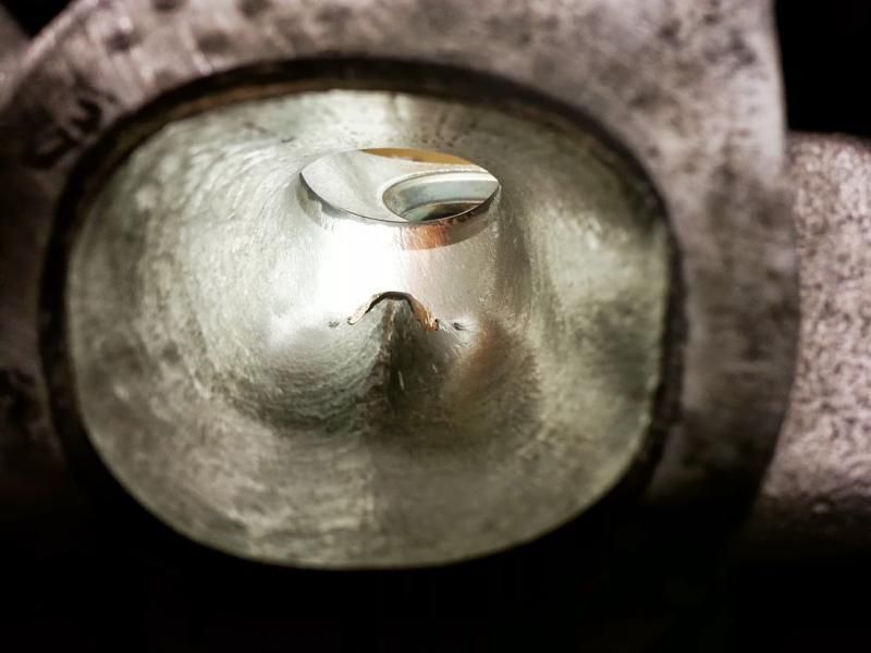
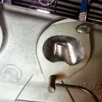
Sorry for the long delay. Been crazy busy with work and the commute. I finally finished the porting. I haven't had the chance to get back on the flowbench though, since I work at a different shop. You can see the modified exhaust port compared to the stock. The floor was very modified, the port shape was changed. The intake was cleaned up, and a lot of short turn work. The basic port is mostly untouched.
[/img]
[/img]
-
- Posts: 4163
- Joined: Feb 12, 2006 12:00 PM
- Location: Richmond, VA