? on MegaSquirt and 179 final checks before startup - take 2

Discussion pertaining to positive pressure E28s.
Post Reply
9mil
Posts: 268
Joined: Sep 27, 2010 8:43 PM
Location: Atlanta, Ga

? on MegaSquirt and 179 final checks before startup - take 2

Post by 9mil »

So I have reached a point with my M106 rebuild/ transplant that some testing is required before I plug the megasquirt in and I’m not really liking what I am finding-
History- 1987 635csi – removed motor and replaced with an M106 unit I rebuilt from the crank up. Drove it around the block using a TCD chipped 059 ECU, Begi – not boosting, just verifying it ran.
So, for some reason, I decided to go with MS at that point and started assembling parts. I got pretty much everything together and fried my MS due to some bad wiring on a relay board for my first attempt- this was utilizing the 059 ecu plug and harness as a base for what was there and I wired up the additional sensors directly to the MS- short story: screwed it up and don’t want that to happen again. So, I decided to go about this the right way (or at least the rightest way I can think of) - picked up a motronic 179 harness and c101 adapter plug and peeled off the old, put on the new… I had Symtech fix my MS and build me one of Goathumpers 179 adapter boards.
Image
I feel pretty confident I got all the sensors on (60/2, IAT, MAP, WB o2- I think that sums it up for running at least) and I plugged the 179 harness into the adapter board and plugged in my relay cable that will plug into my MS unit in the near future. So before that I have checked the connectivity to sensors- all good. It’s the voltage im worried about –specifically with the key OFF.
With key off:
.22v on PIN 4 and 5 and 27
.63V on 25
12V on 28,32,33,34,35,37
10.91V on 30

With the Key ON I get all the same, with the exception of 5V on PIN 23

So I swapped my relays and couldn’t get power on 28-37 with key on OR off. I have the 12V jump pole which supplies 12v to the system wired to the battery- I am 99% sure this is correct- its HOT all the time.
Image

Image

Image

I cant seem to find much on the adapterboard wiring and expectations for pinouts with ignition values, but from some quick research – those last pins are injector related and don’t require 12V all the time.

Does anyone have any info on the Goathumper adapter board? I have found his post over on R3V but they don’t hold any of this info… and I not really sure that is the issue at all- I am thinking something with my harness swap might be the culprit… so I am going to pin that out tomorrow. I think there are a few folks on here that have done the 179 swap to use the adapter board and wanted to get some of their experiences with the board and the harness. I am playing it cautious on this one as I have paid for stupidity already!

Any MS folks near Atlanta by chance? I know DIY autotune is but they tend to be pretty anti getting involved in this kind of stuff – hence the DIY part… they and Symtech are extremely helpful on MS questions though.

a bit messy in the engine bay currently- just trying to get a result before tidying everything up.

Thanks for any info!
9mil
Posts: 268
Joined: Sep 27, 2010 8:43 PM
Location: Atlanta, Ga

Post by 9mil »

Found a 1.3 pinout- just in case someone else needs it-
http://84.45.115.78/e30zonewiki/index.php/ECU_Pinouts

I figure ill see what the key on and key off values are and report on that.

9
Xenocide
Posts: 3370
Joined: Jun 08, 2008 4:29 PM
Location: Atlanta, GA

Post by Xenocide »

Great resource! That's the best layout I've seen yet. I do have a goathumper board and can trace stuff down if you need me to. I'm at work now, but I can do it when I get home. Let us know what what you find on the engine harness key on/key off test. My schedule is really chaotic, but I am local. Give me a shout if you really get in a bind.

I can't tell exactly what problem you're describing, but I will tell you that there has been some trouble with the footprint of the transistors on the adapter board. Was it tested? It seems that an incorrect footprint was specified on an earlier version of the board, the footprint was corrected on the later version (0.05 IIRC). There's still some confusion as to which transistors to use though, as the footprint specified was for a 2n2222 and the BOM called for a 2n3904 (or something along those lines, I don't recall exactly). The two different parts are functionally very similar, but the pin order is reversed. So you can use them interchangeably, but you need to install them backwards. I don't recall which ones are needed on the v0.05 board (the one I have), but I'll let you know when I get home tonight.

The 5v on pin 23 is from the LC-1, and is normal. With the key off you shouldn't be seeing voltage at the fuel injectors though (pins 32-35). I don't recall what pin 30 is up to on the goathumper board, I'll have more details tonight.
9mil
Posts: 268
Joined: Sep 27, 2010 8:43 PM
Location: Atlanta, Ga

Post by 9mil »

Dude- there is beer in your future ( if you drink beer of course)
Thank you- I am going to go out and pin out with key on key off the engine harness connection and see if I can't isolate the issue a bit.
Ill report back tonight on that- what part of town are you in? And were you at caffine and octane this morning? Sick amount of people as it was the first pretty day in a long time!

Phil
Xenocide
Posts: 3370
Joined: Jun 08, 2008 4:29 PM
Location: Atlanta, GA

Post by Xenocide »

I was hoping to be there, work :(

I just tested my board, and what I've measured doesn't quite add up. I'll have to suck the transistors off this board before I can tell you for sure what's what. I'll have some time after school tomorrow to do so. Bug me if I haven't updated this thread. The company that you got your goat humper board from, did they test it? I'd like to think that they knew what they were doing, but I haven't even had time to go thru my setup and fix it yet :(
9mil
Posts: 268
Joined: Sep 27, 2010 8:43 PM
Location: Atlanta, Ga

Post by 9mil »

Verified 2008 v .05 nimick adapter board -

On the 55pin motronic 1.3 harness:

Key off:
12v on 18, 36,

Key on:
12v on 1, 18, 27, 36

Going to confirm my starter and FUel relays are in the right spots now.
9mil
Posts: 268
Joined: Sep 27, 2010 8:43 PM
Location: Atlanta, Ga

Post by 9mil »

Xenocide wrote:I was hoping to be there, work :(

I just tested my board, and what I've measured doesn't quite add up. I'll have to suck the transistors off this board before I can tell you for sure what's what. I'll have some time after school tomorrow to do so. Bug me if I haven't updated this thread. The company that you got your goat humper board from, did they test it? I'd like to think that they knew what they were doing, but I haven't even had time to go thru my setup and fix it yet :(

I got it blank from DIY- the last one they had... And had symtech build it- they seem pretty spot on, but this is a one off piece, so there is a real chance something is going on there. Ill start researching- thanks for the help!
winfred
Posts: 2839
Joined: May 12, 2007 7:15 PM
Location: loserana

Post by winfred »

got my goathumper board back when they were new and it didn't fucking work then, had to have peter florance de bug it for me, i got hosed with faulty instructions and a defect on the silk screened markings, i have no idea where ryan is now but i remember him vanishing back when these first came out, may of been military or may of flaked, i stopped following things on e30 tech before anything came up on where or what
9mil
Posts: 268
Joined: Sep 27, 2010 8:43 PM
Location: Atlanta, Ga

Post by 9mil »

Great- yet another attempt to make things easier..... Makes things harder!

I guess all I can do is verify I have the 1.3 harness right then go from there and bang it out one problem at a time till
It mimics a working unit
9mil
Posts: 268
Joined: Sep 27, 2010 8:43 PM
Location: Atlanta, Ga

Post by 9mil »

Contacted Pete Florence just incase he wants to take another crack at getting one to work again ;-)

Hopefully firstfiver may show up :-)
9mil
Posts: 268
Joined: Sep 27, 2010 8:43 PM
Location: Atlanta, Ga

Post by 9mil »

Got the word back- it's headed to Pete later today... I'm gonna nip this in the bud... Or at least get Pete to nip it in the bud.

I really didn't want xenocide taking his stuff apart if we can get around that. I still need to verify my harness is installed correctly though!

Thanks-
Xenocide
Posts: 3370
Joined: Jun 08, 2008 4:29 PM
Location: Atlanta, GA

Post by Xenocide »

I think I'll still do it, if only to put a schematic online and solve my problems. This is stupid, it's a decent product, but the documentation is fucking awful.
9mil
Posts: 268
Joined: Sep 27, 2010 8:43 PM
Location: Atlanta, Ga

Post by 9mil »

Yea - I plan on asking what was wrong if he finds something aria- then get symtech's assembly instructions.... Just to get it documented.
marc79euro645
Posts: 513
Joined: Dec 08, 2008 11:33 PM

Post by marc79euro645 »

If I were you I'd get rid of the adapters, get a color coded,labeled ms harness from diy and wire it as per their color schematic, so simple. You will never go back to the bosch ecu so why try to use the wiring.
good luck
marc
9mil
Posts: 268
Joined: Sep 27, 2010 8:43 PM
Location: Atlanta, Ga

Post by 9mil »

I have one of those- it's now a relay cable.... I was trying to keep it somewhat stockish looking and cleanly done - I would have been done a while back had I went with a relay board and wired directly.... What's done is done and I like to throw money at problems ;-)

It's what I'm good at!
Xenocide
Posts: 3370
Joined: Jun 08, 2008 4:29 PM
Location: Atlanta, GA

Post by Xenocide »

I'll probably make a separate thread for this, but just in case anyone stumbles on this thread:

I started reverse engineering the goathumper v0.05 board. I found some questionable design decisions, and I'm still not sure exactly what's going on with the pots, but here's a rough outline of the rest.

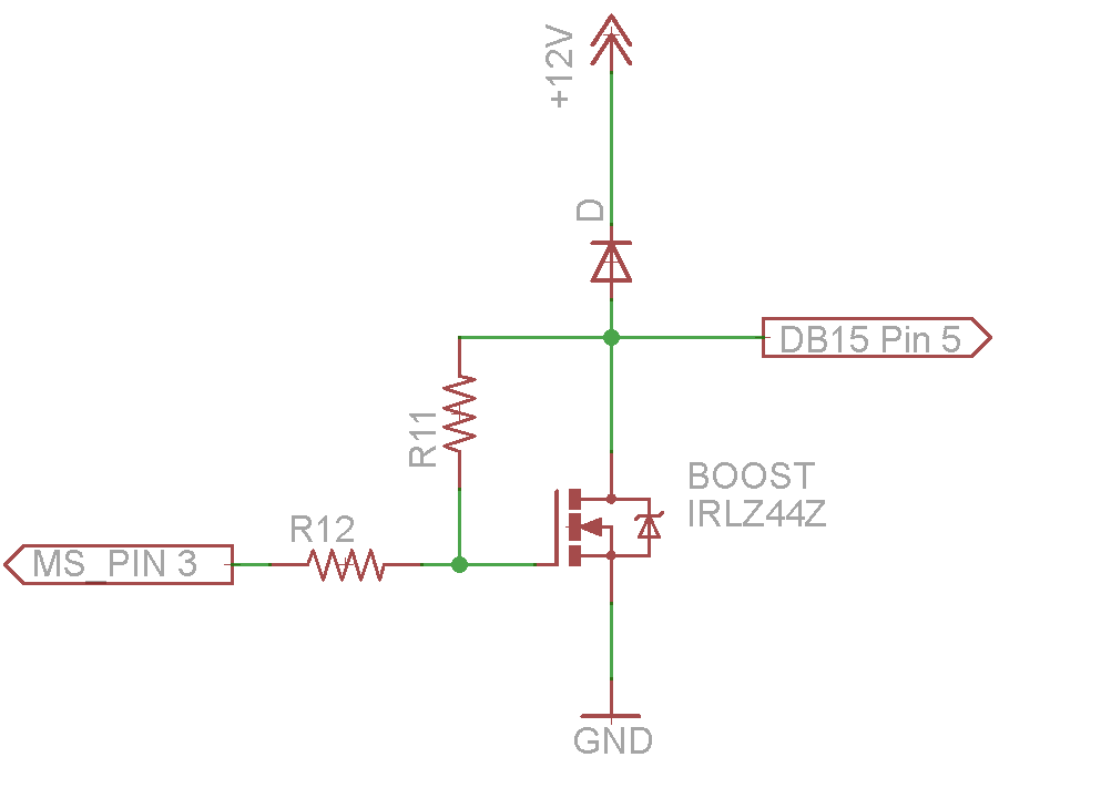
Boost circuit
Image
Fairly simple, it uses an N-channel mosfet to switch (or PWM) a boost solenoid. I couldn't determine the diode number since it was already populated, but it's the same part as all of the other diodes (1n400x). The diode is in place to snub any transients produced by the collapsing magnetic field in the solenoid.

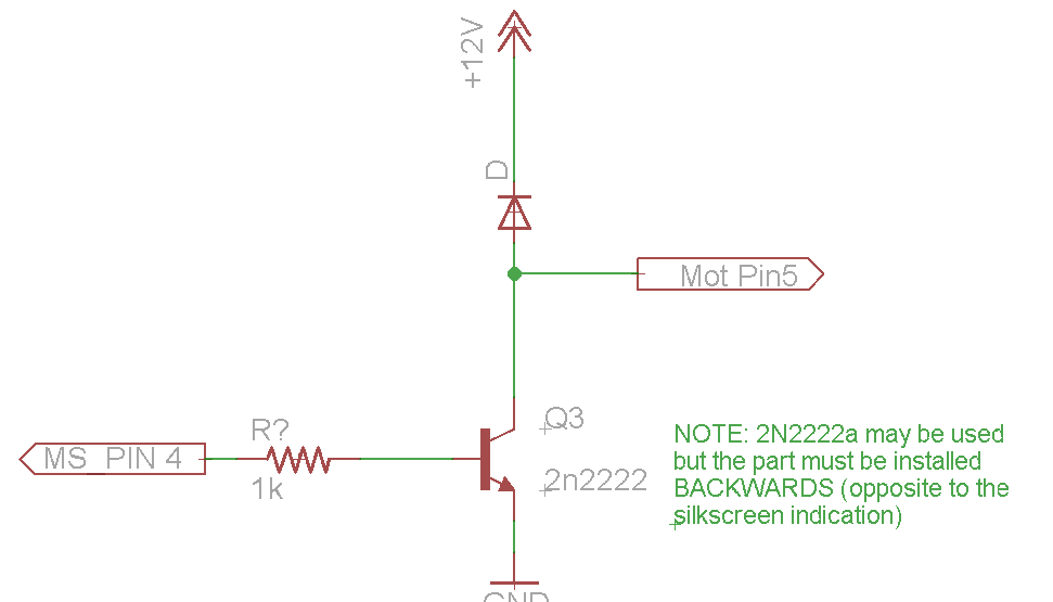
Evap Purge
Image
Again a fairly straightforward circuit, an NPN transistor is used to ground pin 5 on the motronic harness (the evap purge valve). Again a diode is in place to squash any high voltage flyback from the valve. I couldn't read the resistor number as it's populated on my board, but it's very easy to find. If anyone has a picture of an unpopulated board that'd help.

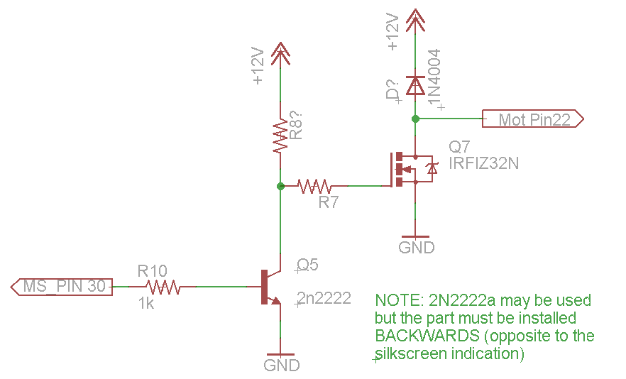
O2 Sensor Heater
Image
This circuit uses an NPN transistor to trigger an N-channel mosfet to run the heater. I will have to play with this circuit a little, I never used it. I have my LC-1 on a separate switch.

I've found that there's some funkyness going on with Q4 as well, I have that diagram coming soon. It's the one that triggers the main relay I believe.

TLDR

The silkscreen on the v0.05 board is correct IF you're using 2N4401 transistors. If on the other hand, you order 2N2222 transistors, you must install them backwards. The goal is to ground the emitter, which is Pin 1 on the 2n4401, but pin 3 on the 2n2222a. Otherwise the transistors can be used interchangably.
Last edited by Xenocide on May 25, 2013 8:53 AM, edited 1 time in total.
9mil
Posts: 268
Joined: Sep 27, 2010 8:43 PM
Location: Atlanta, Ga

Post by 9mil »

Good info- you must have graduated to find that kind of time!

You don't happen to have your old harness still by chance? I'm thinking about swapping back so I can actually move this thing- it's been sitting for about 7 months waiting on something or othe megasquirt related! I'm tired of looking at it
Xenocide
Posts: 3370
Joined: Jun 08, 2008 4:29 PM
Location: Atlanta, GA

Post by Xenocide »

I did indeed finish school, graduation is Saturday. :banana:
I should still have my 1.0 harness (and a megasquirt adapter harness for it) though I haven't clapped eyes on it in some time. I'll rummage through the garage and see if I can find it tomorrow.
9mil
Posts: 268
Joined: Sep 27, 2010 8:43 PM
Location: Atlanta, Ga

Post by 9mil »

Congrats on graduating- well done.... Lets get some beers next week!
Xenocide
Posts: 3370
Joined: Jun 08, 2008 4:29 PM
Location: Atlanta, GA

Post by Xenocide »

I looked, but couldn't find the harness, I know I've got it somewhere, but my garage is a fucking nightmare right now. I know that mine is hacked in at least one or two places anyway. It'd probably be worth more to me than the market price anyway. I'd be happy to help you work out your megasquirt shit though.

I'd love to go for beers, maybe even put out the word and some more of the GA guys will get together :banana:
9mil
Posts: 268
Joined: Sep 27, 2010 8:43 PM
Location: Atlanta, Ga

Post by 9mil »

I'm in.... Pretty bad over here currently.... My 540 wouldn't restart at the gas station this morning- my S60R was supposed to be delivered tonight but got pushed till tomorrow and I am about 7 beers in with a buddy on my iracing.com sim at Spa and my lap times are suffering!

Appearntly one can drink their issues away!
9mil
Posts: 268
Joined: Sep 27, 2010 8:43 PM
Location: Atlanta, Ga

Post by 9mil »

And to my disbelief.... IT STARTED!

Now the work begins
Xenocide
Posts: 3370
Joined: Jun 08, 2008 4:29 PM
Location: Atlanta, GA

Post by Xenocide »

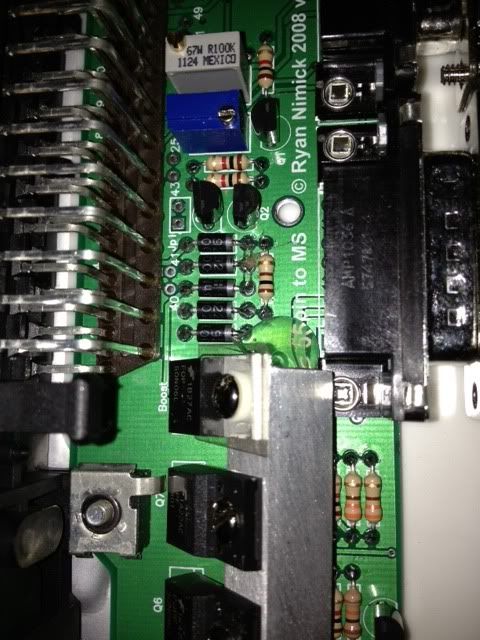
Awesome! Any chance we could get a pic of the adapter board?

I'm doing the drinking thing tonight, but I promised myself I'd get back in the garage this weekend.

Also my laptimes on rFactor and LFS get better until around the 5th or 6th beer, then people start dying. Yet another project to work on, I really need to clean the garage to put my sim together.
9mil
Posts: 268
Joined: Sep 27, 2010 8:43 PM
Location: Atlanta, Ga

Post by 9mil »

Image

http://s828.photobucket.com/user/phil40 ... sort=3&o=1

Photobucket mobile sucks-

Ill post better pics and some explanation when I get a second. Absoulutly covered up at the moment!

Thanks
Post Reply