535is Homebrew Turbo (ex 633 Callaway) - 2024 Update
Re: 633CSi Turbo - 12/22/2017 - Not Really Callaway Anymore
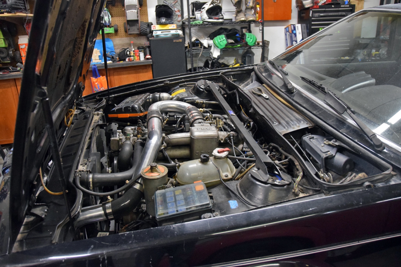
It was difficult to fit! I left the bolts loose to be able to clock it out of position before clocking it back once installed. This gave me the necessary clearance to the inner fender. I actually jacked up the engine partially for extra clearance and it was tighter than the Callaway orientation to fit the combo past the exhaust studs.
The #5 upper exhaust nut was difficult, but doable to tighten. Hopefully I don't have to remove this setup for quite a while!
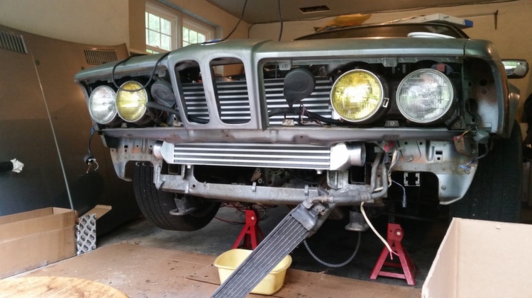
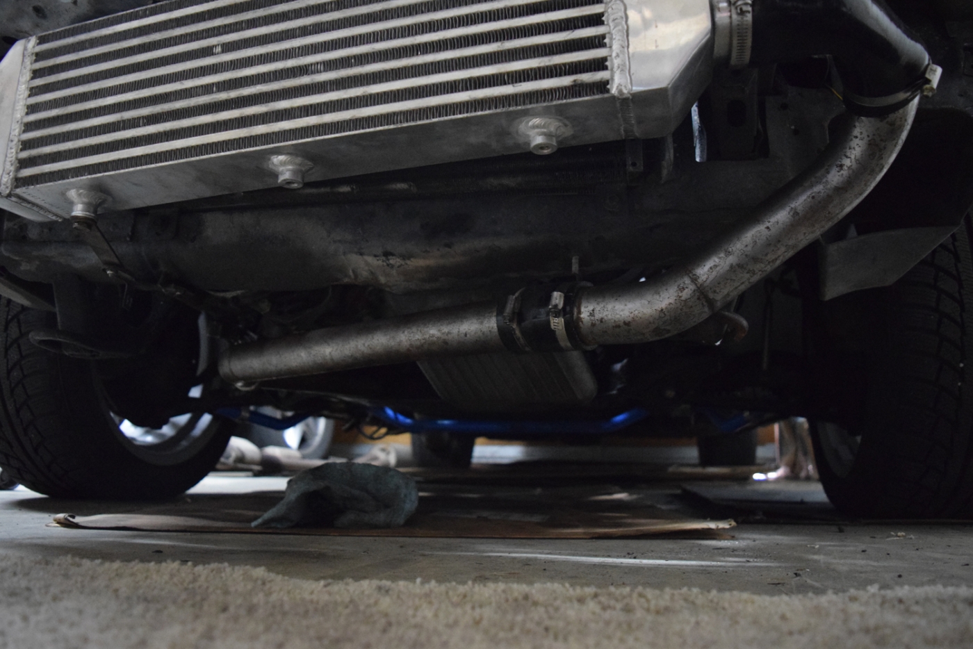
Here's the intercooler and old piping. The bend on the right is different now and may change when I play with it in the next few days.
The #5 upper exhaust nut was difficult, but doable to tighten. Hopefully I don't have to remove this setup for quite a while!
Here's the intercooler and old piping. The bend on the right is different now and may change when I play with it in the next few days.
Re: 633CSi Turbo - 12/22/2017 - Not Really Callaway Anymore
Seems like it would be easier to route the cold side of the charge pipe up the drivers side. Either reverse mount the throttle or run a 180deg bend off the throttle in the stock location.
Re: 633CSi Turbo - 12/22/2017 - Not Really Callaway Anymore
I was thinking about this actually... I would have to rework my icv and divertor valve but was going to investigate. so I may run non intercooled until I think about it some more. ill look at routing the charge piping both ways before I decide
Re: 633CSi Turbo - 12/22/2017 - Not Really Callaway Anymore
Since you're running MAP you can run the diverter/blowoff anywhere between the turbo and throttle. There's no need to recirculate it - although it can be a little louder when dumping to atmosphere.
By the looks of it you could probably also leave the ICV in the same location and just weld on a 1" (maybe its 7/8", I can't remember) bung.
That would clear up a couple feet of piping.
By the looks of it you could probably also leave the ICV in the same location and just weld on a 1" (maybe its 7/8", I can't remember) bung.
That would clear up a couple feet of piping.
Re: 633CSi Turbo - 12/22/2017 - Not Really Callaway Anymore
Great job Tom. My experience has been that using the b35 cam does result in a 4-500rpm shift int he curve but doesn't make the car accelerate faster.
Re: 633CSi Turbo - 12/22/2017 - Not Really Callaway Anymore
I'm assuming you'd also need the bump in compression to take advantage of the different cam profile.T_C_D wrote:Great job Tom. My experience has been that using the b35 cam does result in a 4-500rpm shift int he curve but doesn't make the car accelerate faster.
Re: 633CSi Turbo - 12/22/2017 - Not Really Callaway Anymore
Thanks for the comments guys.
For the cam, I had to replace it anyway, so why not get one with more lift? I figure the cam will help the engine breathe as far as getting the charge in and out to the turbine. I was going off of a post by Paul Burke suggesting that the B35 cam is probably the best available for turbo (besides his custom grind and others, $$$).
With the torque curve shifted up slightly, I think I will be able to better use the torque at the track.
Last night I wired the TPS and started it up and came into a smooth idle! I need to work on readjusting my exhaust to be able to get an o2 signal, but it is coming along. I am thinking the signal noise is gone but need to look at it a bit more to tell for sure.
Re: 633CSi Turbo - 12/22/2017 - Not Really Callaway Anymore
Unfortunately PB has never owned a turbo m30 personally nor tested any cams for that application. You will be fine. You just have to gear the car accordingly.tschultz wrote:Thanks for the comments guys.
For the cam, I had to replace it anyway, so why not get one with more lift? I figure the cam will help the engine breathe as far as getting the charge in and out to the turbine. I was going off of a post by Paul Burke suggesting that the B35 cam is probably the best available for turbo (besides his custom grind and others, $$$).
With the torque curve shifted up slightly, I think I will be able to better use the torque at the track.
-
- Posts: 66
- Joined: Apr 06, 2015 9:24 PM
- Location: colorado springs
Re: 633CSi Turbo - 12/22/2017 - Not Really Callaway Anymore
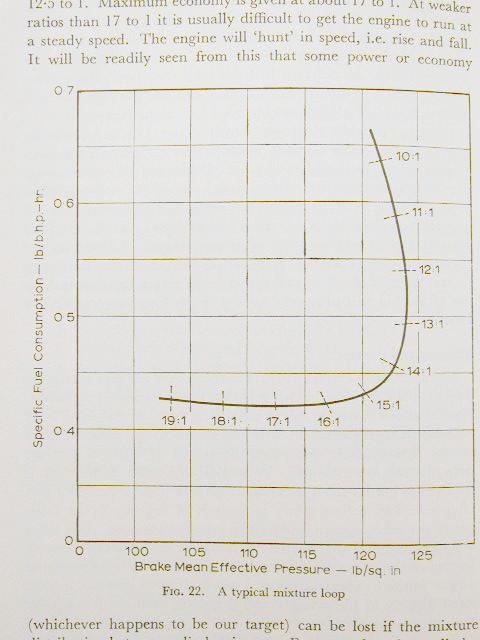
Since you may have to revisit your tune, this link has some useful information. I'll copy it in case the website goes down, but the image was useful to see fuel consumption vs BMEP, or max power.
http://ackthud.com/shawnfogg/mixture.htm
So even running at 11:1 doesn't lose much power as compared to max power at 12.8:1For the most complete combustion gasoline usually needs to be burned at a ratio of 14.7 parts of air to 1 part fuel. This air to fuel ratio (AFR) is called stoichiometric or Lambda = 1. This is just a ratio between air and fuel. For example all of the following are at the same AFR:
7.35 lbs of air to 0.5 lbs of fuel
14.7 lbs of air to 1 lbs of fuel
147 lbs of air to 10 lbs of fuel
Obviously the amount of air and fuel being burned is totally different between each example but the AFR for each is identical.
14.7:1 AFR is normally considered the best trade off between emissions, fuel economy and power production.
Running LEAN is when your AFR has more air to it. The AFR is greater then 14.7:1 (Lambda >1) for example 16:1 AFR is lean. Running lean increases emissions, increases heat, usually increases fuel economy, reduces power and increases the chances of knocking.
Running RICH is when your AFR has more fuel to it. The AFR is less then 14.7:1 (Lambda <1) for example 13:1 AFR is rich. Running rich increases emissions, usually decreases heat, decreases fuel economy, increases power (to a point), decreases the chance of knocking. Running rich for long periods of time can cause deposits to build up on the plugs and O2 sensors (fouling) and can clog your catalytic converter. Maximum power is usually obtained running around a 12.3:1 AFR. Going richer then that will cost a little power but you loose less power then being leaner then 12.3:1. This can be seen in the graph below.
The above graph is taken from 'The Sports Car Engine: Its Tuning and Modification' by Colin Campbell. The graph shows basically how much pressure is created by burning gasoline at different AFRs and also how much fuel is consumed in doing so. Highest power will be achieved at highest pressure (most force pushing on your pistons).
When you are cruising and idling (the emissions cycle) the DME uses your oxygen sensors ( O2 sensors) to determine what AFR the engine is running at. The O2 sensors sense how much O2 is in the exhaust and send a voltage signal to the DME to give the mixture. Different manufacturers of O2 sensors send different voltage signals to the DMEs they are used with. However the DMEs logic behind the O2 sensor data is the same.
Re: 633CSi Turbo - 12/22/2017 - Not Really Callaway Anymore
Good information-- that is a good plot to have to understand the affect of AFR on power. I did notice the power drop off on track when I ran the BEGI RRFPR and ratios hit 10.5:1.
Good news. I got the car started and the exhaust was able to fit up after some adjustment.
Here's a short video before I had the downpipe and wastegate dump fully sealed. There is not intercooler, as you can see from the video-- I am running it this way until I rethink piping.
https://www.youtube.com/watch?v=z3yKg8rsC4k
I drove it today and seem to have much better signals than with the old wire harness. I will do more test drives and video as the weather warms up. 15F and my thick engine oil didn't get along real well for the test drive.
Here's a sample idling after the test drive around the block:
And my current spark/VE tables after a very brief autotune
Pictures and videos to come!
Re: 633CSi Turbo - 12/22/2017 - Not Really Callaway Anymore
How much filtering are you using on the AFR?
Re: 633CSi Turbo - 12/22/2017 - Not Really Callaway Anymore
It will be warming up enough to go for a drive tomorrow I think. Hopefully I'll be able to drive it with some boost and datalog a little bit.
Lag factors:
MAP: 50
RPM: 40
TPS: 75
AFR: 25
CLT/MAT/Battery: 30
I'm also investigating intercoolers and looking at a unit 23x10x2.5. Thinking of placing it where my aux fan used to live. This unit would be about twice the size of my current intercooler.
Not quite as big as this one, but similar. I just need to take a few more measurements for piping:
Thinking about routing the inlet up from the drivers side, but I haven't decided yet.
Re: 633CSi Turbo - 12/22/2017 - Not Really Callaway Anymore
I had a chance to take the car on a 25 minute drive to make sure that air was bled from the radiator and gauges were all working.
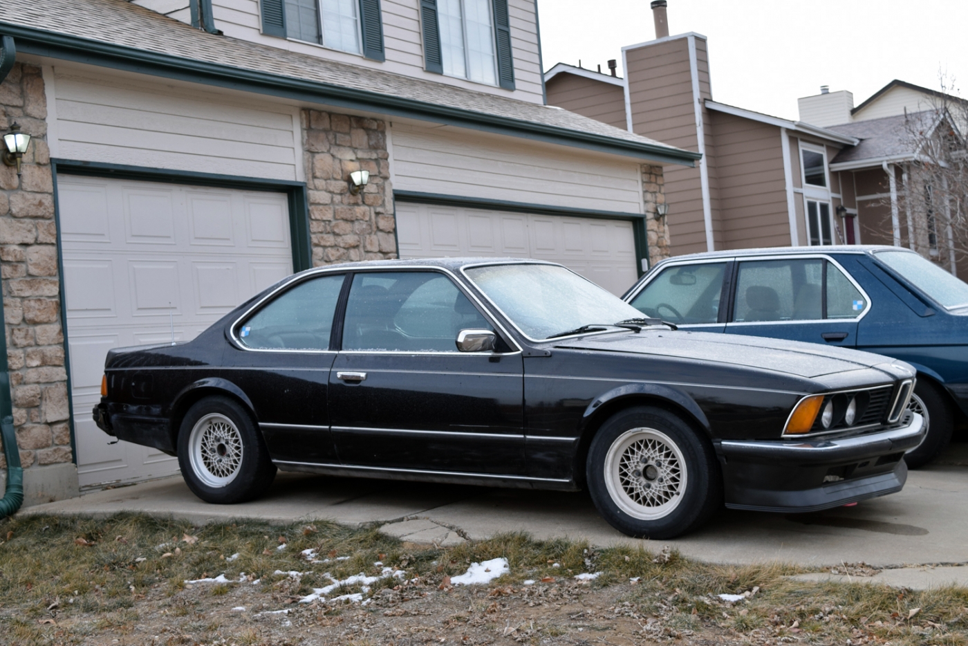
A photo with the winter tires-- BBS Mahle RA's 15x7 et11.
I ran without the intercooler and was certainly surprised to see that with a brief adventure into positive pressure, AIT's climbed above 150F (it was 50F ambient).
Here's a datalog also showing how my signal noise has cleaned up too
For some reason my wastegate didn't seem to want to open so I actually hit boost cut at 160kpa. It freaked me out a bit at first until I realized what was happening. Glad to know it works... next will be to figure out why the wastegate didn't seem to open... I was expecting a scream due to the open dump at the moment, but I didn't have anything.
More slow progress to come. I will be fine tuning accel enrichment, VE table and such. I'm glad to say cold start and warmup enrichment was working the other day as the car started in 15F.
Re: 633CSi Turbo - 12/22/2017 - Not Really Callaway Anymore
All my parts arrived so I was able to make some progress today!
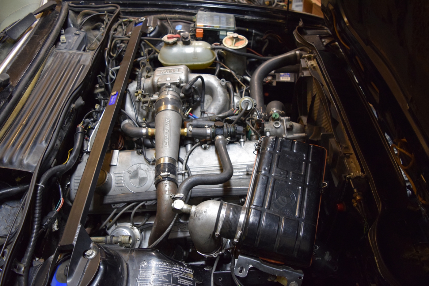
First, the setup without the intercooler:
I had been investigating intercoolers and read a lot of theory but a few things really stood out.
-It should be sized to the flow requirements of the engine...
-Get the unit with the least amount of pressure drop (and most amount of flow)
-Place in area of turbulent air flow for maximum efficiency
-Air to air is really more efficient at the track. Water/air is arguably better for street use.
-Too big of an intercooler may simply take more time for you to reach boost threshold than the appropriate unit.
However, for track application, you need the largest intercooler possible to be able to dissipate heat after continued hard use. The larger the surface area, the better. Core depth isn't really critical as the deeper you get, there are diminishing returns and added weight.
A great read here if you wanted a bit more detail than Corky Bell's book:
https://www.mishimoto.com/engineering/2 ... selection/
Before I explain what size I selected, I did some reading about charge piping size. Basically, you size similar to the intercooler, as small as possible that will allow the CFM flow requirement. Bends and kinks will add pressure drop and make your system inefficient. As the airflow travels through a smaller diameter pipe, it will speed up. This is fine until the air travels up to a speed around mach ~.4. At these speeds, the total flow really becomes limited. So if the air flow rate approaches even .35 it is time to start thinking about upsizing intercooler piping.
My old setup used 2" piping. According to a few sources this pipe size is (street) rated for ~350hp and ~550CFM.
So for the street, this setup is probably close to the ideal size for use at my airflow levels (~380-400CFM).
2.5" piping: rated for ~575hp and 875CFM!
3" piping: rated for ~850hm and 1250CFM!
It also turns out that the compressor outlet is 2". So I elected to keep this 2".
Another suggestion is to increase pipe size as it steps past the intercooler. The idea is that the step minimizes as much pressure drop as possible post intercooler. I had 2.5" piping that I wanted to make work as it isn't too big to fit. It should provide slightly less pressure drop through to my intake manifold. The turbo will work a little less and outlet temperatures should be less, again generating an overall more efficient setup.
My previous intercooler was a 20x6.5" core. With the new piping arrangement, I decided I should get a bigger one for hot days (I didn't like the intake temps I had with over 20F or more above ambient).
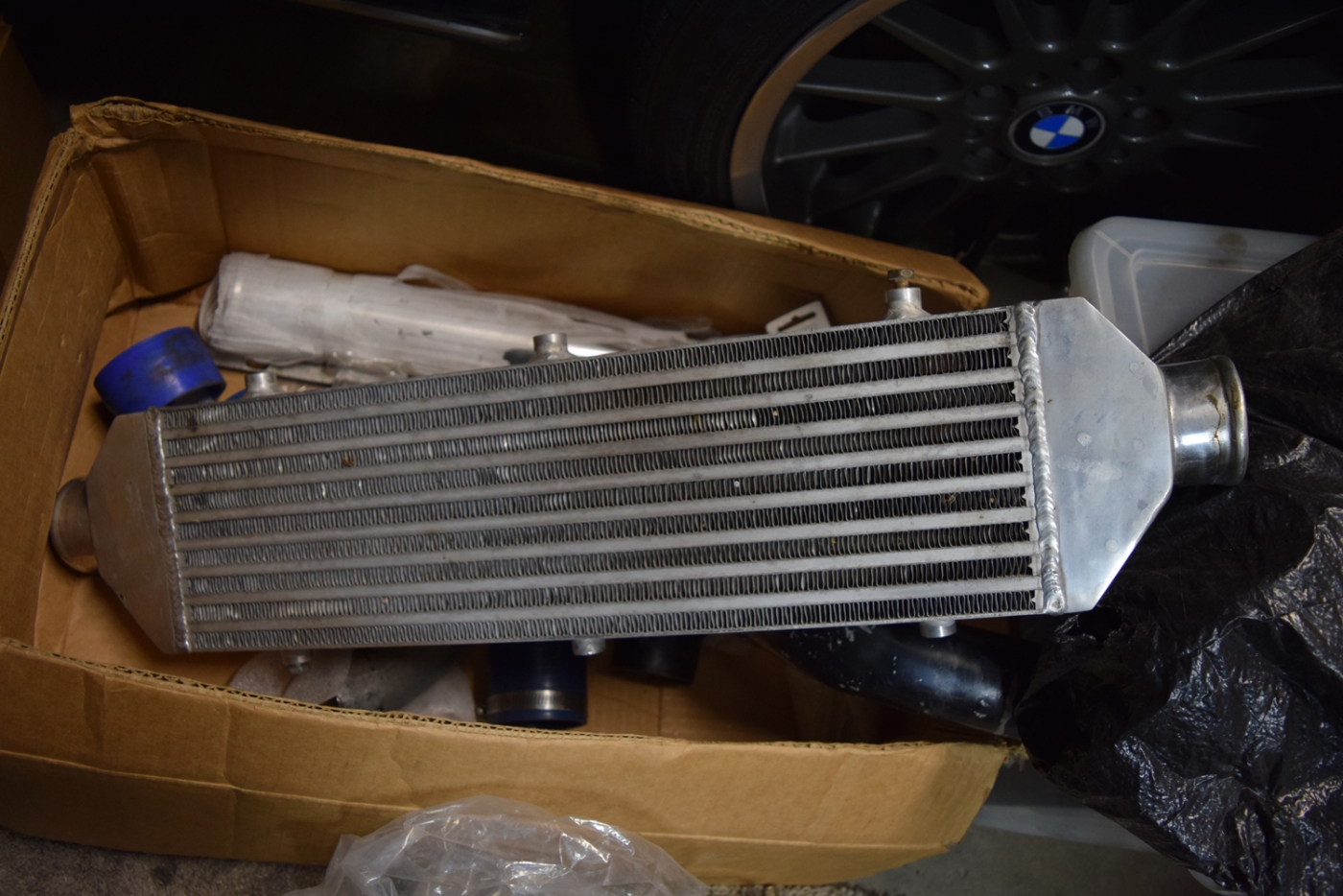
With a new piping layout in mind, I explored intercooler sizes, layouts and placements. Ultimately I decided on an 18x11.5" core manufactured by EMUSA for less than $100 shipped. It is top inlet/out and I flipped this upside down in my head for a pipe routing that I thought would work.
The intercooler was as wide as I could go without modifying the car. It's about 50% larger than the one I had prior. It is placed where the AUX fan used to live, with a total width of 23". This is the size of the radiator cutout and the intercooler lives about 2-3" in front of the radiator. Some horizontal fins ecapsulate the area, so these would have had to be modified to go much bigger.
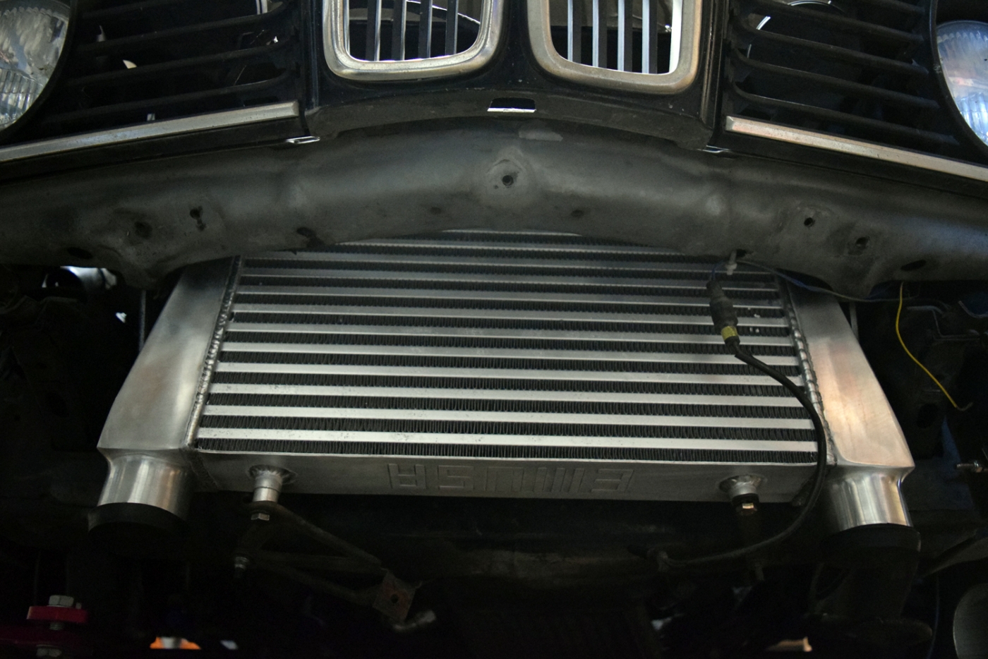
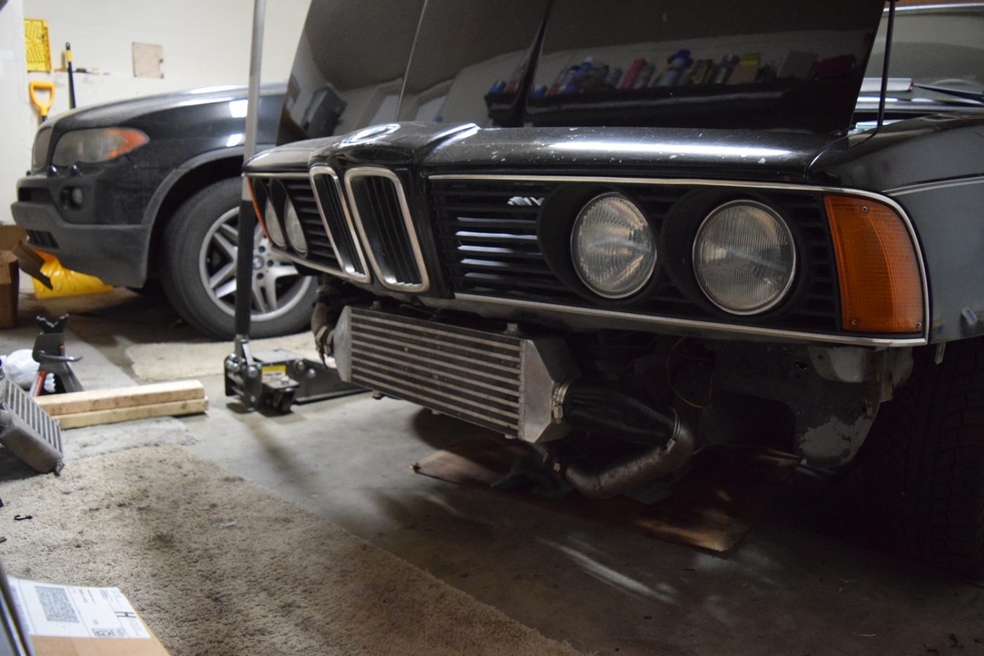
Basically the inlet would come from the engine bay and underneath, or from the headlight opening. With the outlet going up maybe near the headlights. When I tried it out with the intercooler only, it looked like I could make it work.
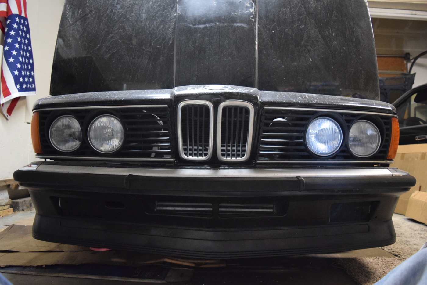
The airdam also had plenty of clearance and fit right up! The openings would be for an oil cooler, but on my car, they are obviously for my intercooler!
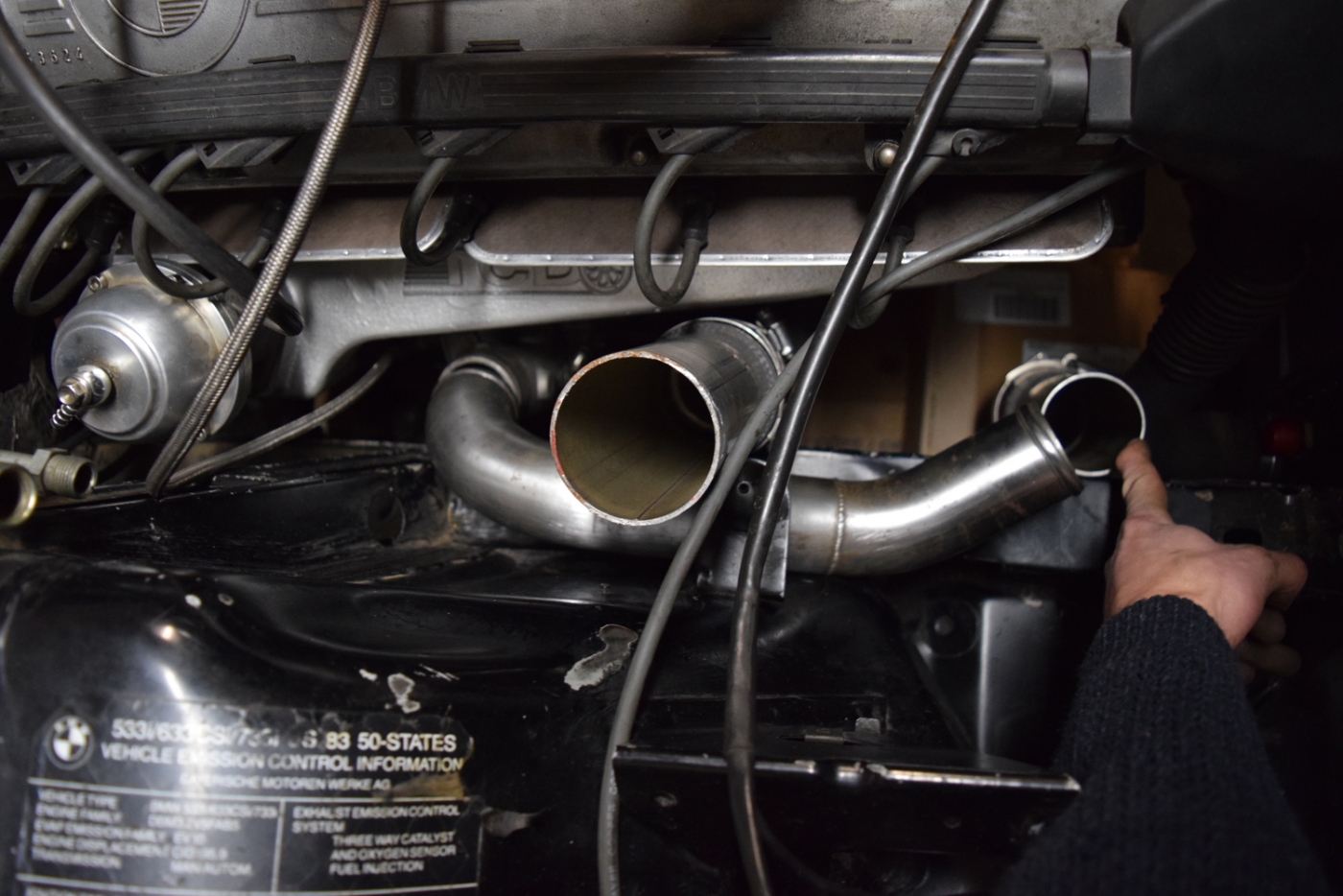
So i checked to see how I could get compressor outlet to fit with the existing air filter setup. Fortunately, this Callaway pipe was close enough to work for me!
Clearance with the airbox in place and couplers attached.
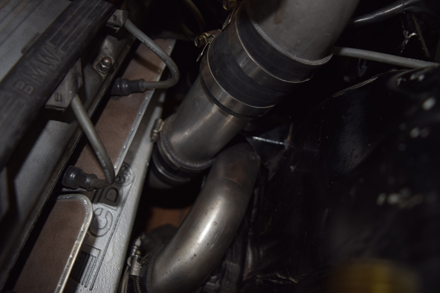
The silicone coupler is a bending reducer opening the pipe to 2.25" gradually as it turns.
There is a 2.25" pipe elbow that bends the air again to be parallel to the ground.
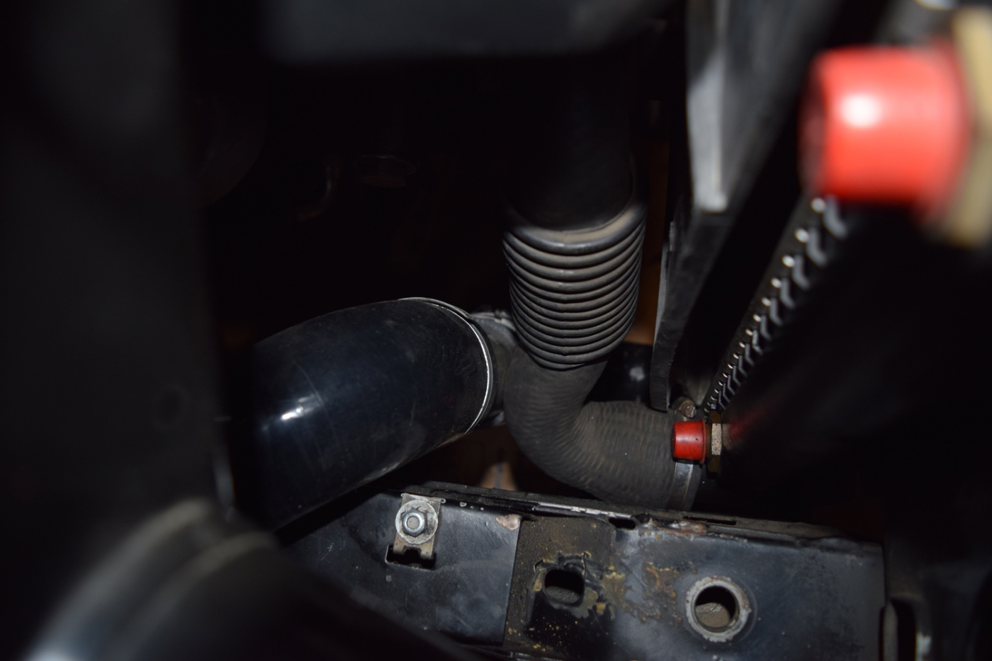
The clearance to the radiator hose is pretty tight, but it isn't touching!
Obviously it comes to the intercooler (it does this in a step to the 2.5" pipe size) and then out and turns up. (I didn't want red, but this was all my supplier had in 2.5" elbows):
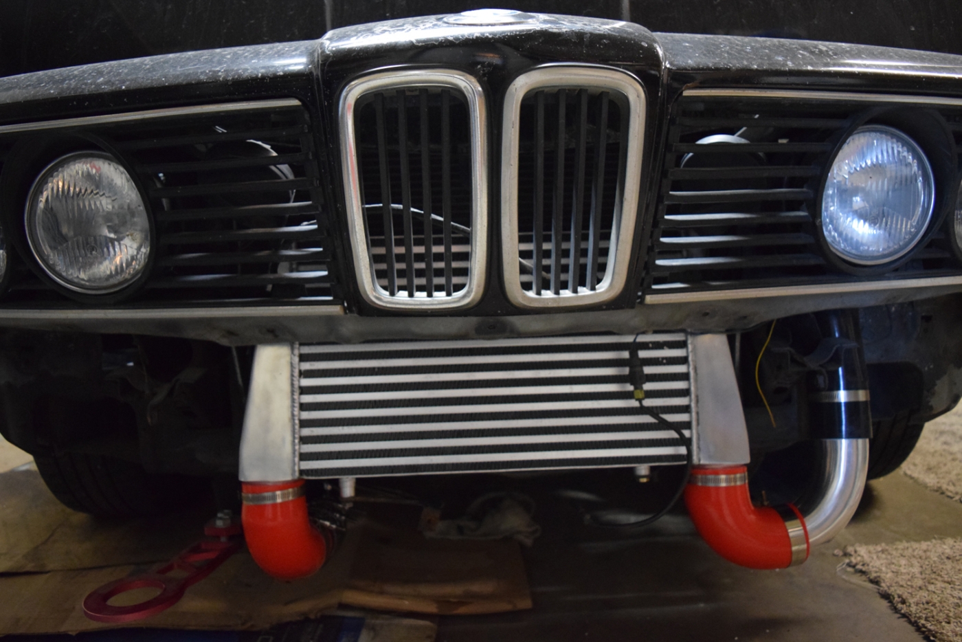
This is where a long silicone coupler brings the air past the headlight mounts and into another elbow into the engine bay.
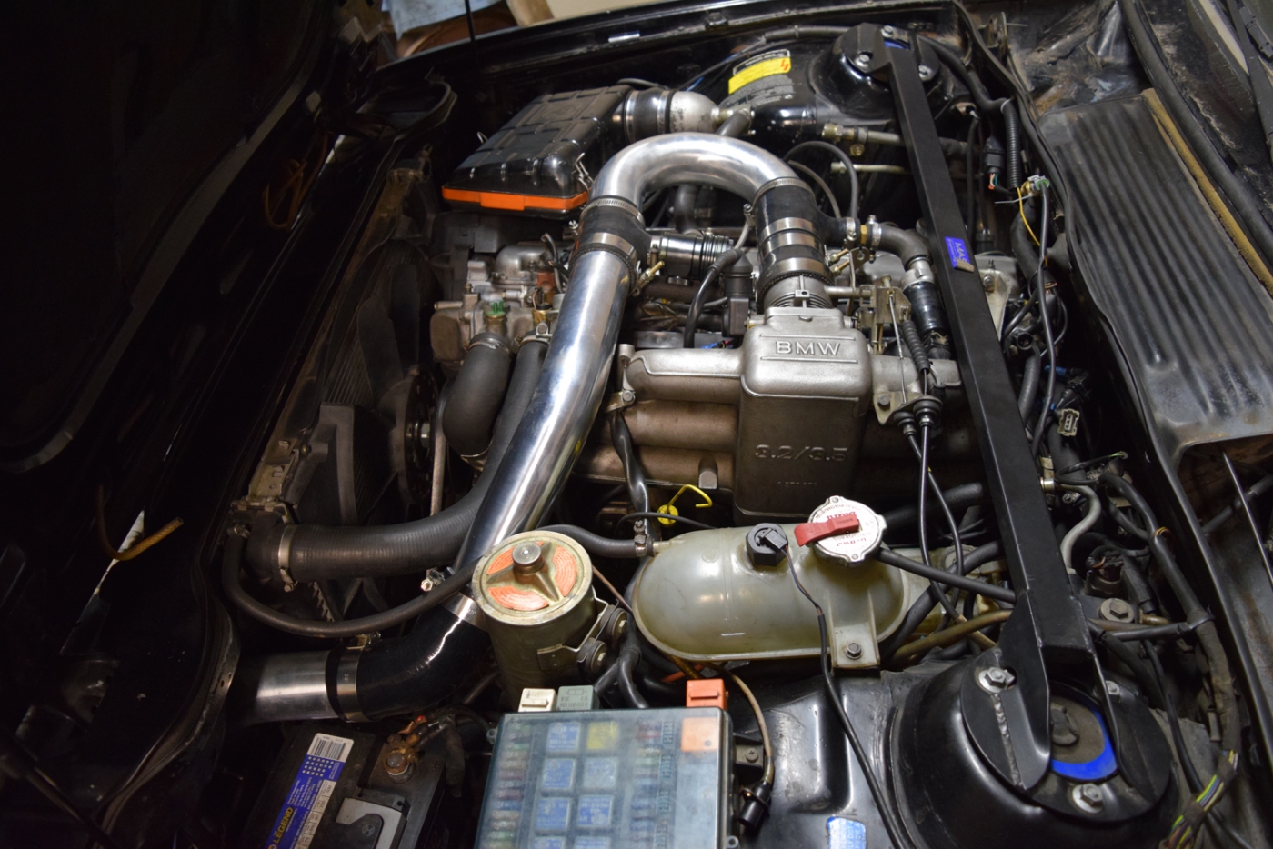
You will notice I am using the same divertor valve as I found the straight coupler with a hose port that would work. I did the same thing for the Idle air pathway as well! There's a step up to the 3" throttle body opening and that's all!
I am going to have a coworker add the AIT sensor on the left end of this 180* pipe, but otherwise that is all that's needed! I had a solution I will probably refine right now that sends diverted air back to the compressor intake, as well as the small amount of blow by that this engine creates.
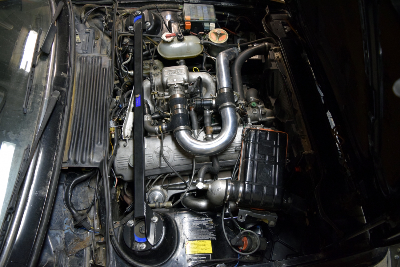
I don't feel like it's super pretty but I think overall it will be quite functional. After a brief test drive, spool doesn't really seem much different than without intercooler piping. Here's the video with the noises inside the car. I still need to finalize the wastegate dump, so this is OPEN with the microphone inside the car:
https://www.youtube.com/watch?v=VXgzQ_6ibo4
More updates to come as weather permits!
Last edited by tschultz on Jan 15, 2018 1:47 PM, edited 1 time in total.
Re: 633CSi Turbo - Not Really Callaway Anymore - 1/14/2018
Well thought out.
Re: 633CSi Turbo - Not Really Callaway Anymore - 1/14/2018
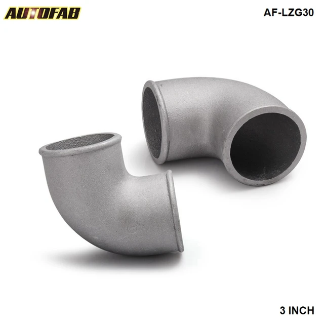
Looks good. You could probably weld on some casted 90s to the inlet/outlet of the intercooler. That would eliminate the bright red and also reduce the clearance to the ground.
Something like this:
Re: 633CSi Turbo - Not Really Callaway Anymore - 1/14/2018
^ i used one of those on the turbo. works perfect. one less piece of shit coupler to mess with
Re: 633CSi Turbo - 12/22/2017 - Not Really Callaway Anymore
lol BURN!T_C_D wrote:Unfortunately PB has never owned a turbo m30 personally nor tested any cams for that application. You will be fine. You just have to gear the car accordingly.tschultz wrote:Thanks for the comments guys.
For the cam, I had to replace it anyway, so why not get one with more lift? I figure the cam will help the engine breathe as far as getting the charge in and out to the turbine. I was going off of a post by Paul Burke suggesting that the B35 cam is probably the best available for turbo (besides his custom grind and others, $$$).
With the torque curve shifted up slightly, I think I will be able to better use the torque at the track.
Re: 633CSi Turbo - Not Really Callaway Anymore - 1/14/2018
Thanks guys,
For now I am ok with the couplers as they will insulate and not retain heat. If they become a problem I may investigate the elbow suggestion (but I don't have the ability weld myself).
My coworker is adding the IAT sensor to the elbow since he can weld aluminum. Maybe later this week I can get the pipe and his help to fix my waste gate dump. Maybe I'll drive the car thursday with the IAT sensor installed... It's supposed to get to 60F.
Re: 633CSi Turbo - Not Really Callaway Anymore - 1/14/2018
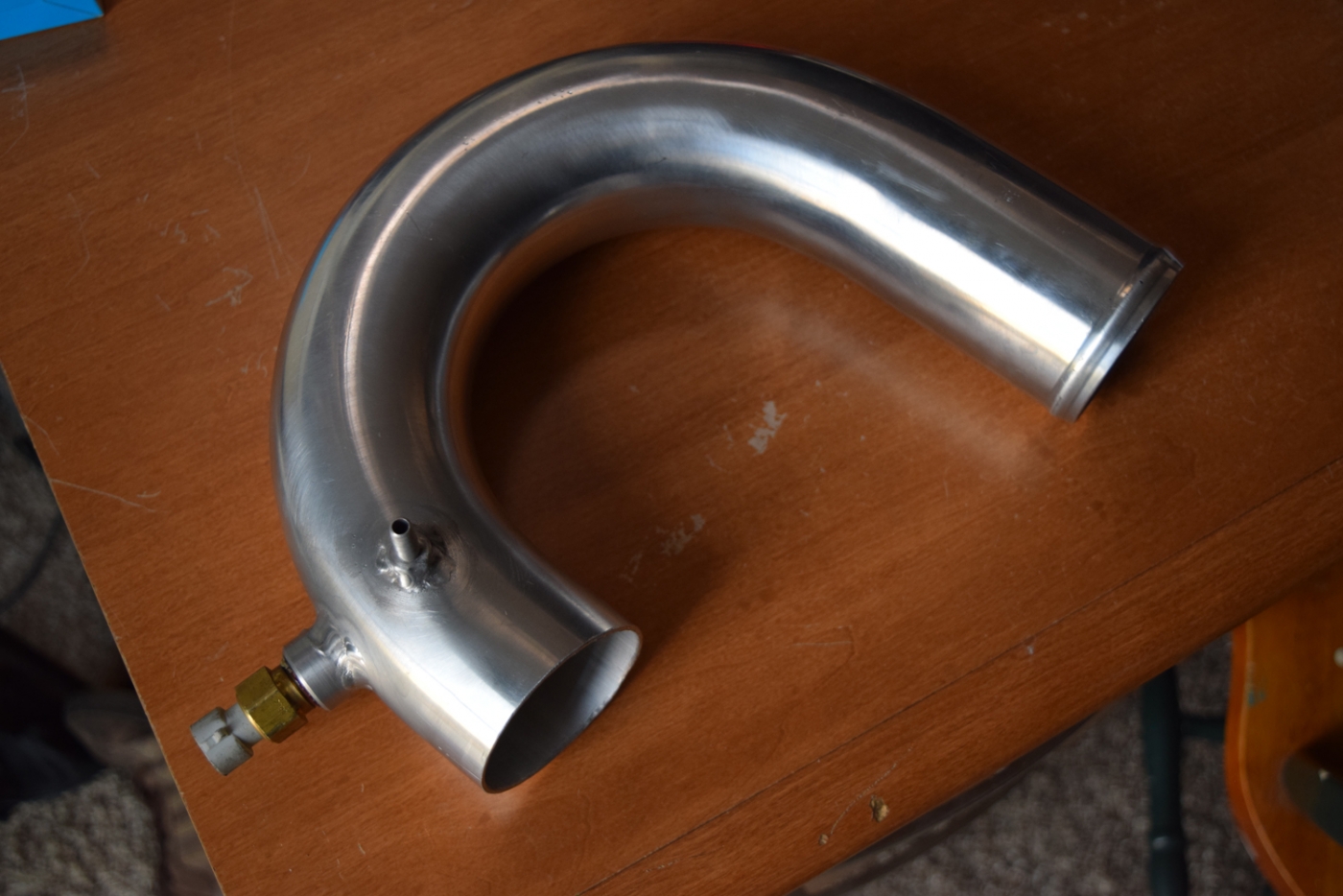
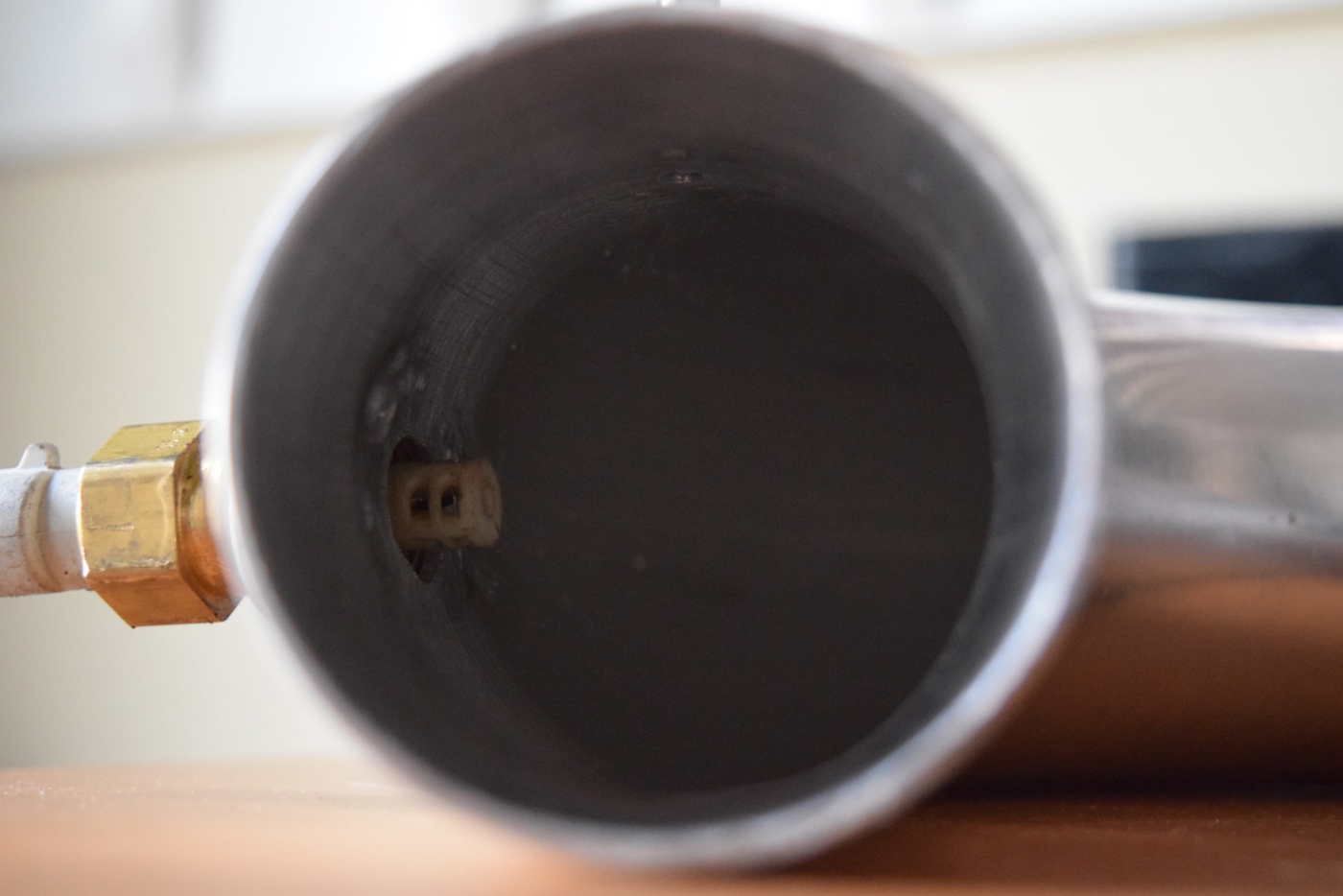
My coworker was nice enough to help me out and weld on the IAT bung and a port for my wastegate signal. The aluminum barb was like $2.00 from Summit Racing and the bung had come with my IAT sensor originally.
My coworker did a great job with the welds and keeping smooth pathways on the inside of the pipe.
I may have him help me finalize my wastegate dump, but I need to find a place to get the right sized piece of tube (1.5" I think). Basically cut and lengthen my current dump.
I was able to drive the car yesterday and get out on the highway since everything seemed to be working. It was ~60F and I was able to get Autotune going to start dialing in my tune.
I removed some timing to be safe and lowered my AFR table in a few places just to continue with tuning.
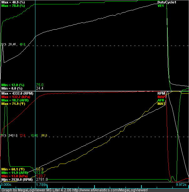
Next up I did a datalog with a WOT run. I was super happy to see that IAT's only climbed about 15F. Much improved over the 50F without an intercooler.
It made sense to plot my base runs on VirtualDyno. I did some reading and found the following:
Ignore the HP values and just look at torque-- I was only trying to plot max torque.
The first run from June 2nd Last year (Orange) was run with my Callaway Log, old noname intercooler and 2" piping at about 6psi. A couple of logs show this curve to be pretty accurate up to the specified RPM using the Smoothing rule of thumb.
In warmer weather I had bumped up the boost to about 10psi and taken a log (Green). It probably isn't a fair pull to use in terms of RPM and gear, but an increase of only 20lb-ft torque is all that this plot indicates. Maybe this is due to the richer fuel mixture, but I didn't extensively test 10psi so I can't really make a judgement on this curve. It was just interesting to see.
The other week I did a quick pull without an intercooler (Blue). This is with the new TCD manifold (ceramic coated), valve job, and cleaned up/opeend up exhaust flange coming off the turbo. Interestingly this log with increased IAT's still gave number similar to the old setup at 10psi. I think the Callaway manifold (sharp edges, poor pulse design) and exhaust flange were choking performance by adding increased backpressure and preventing max flow through the engine.
Finally, the new setup with intercooler and larger charge piping (Red). I know intake temperatures were much lower than all other logs due to ambient air and larger intercooler, but with the same turbo and same boost level this data shows about a 10% increase in performance. I have to do a more scientific datalog to get exact numbers, but at least I can see my changes have made a difference! Also note that max torque was 200rpm later, maybe more as it was still building.
The plan is to fix the wastegate dump and then eventually tune and settle at 8-10psi for track use.
My coworker did a great job with the welds and keeping smooth pathways on the inside of the pipe.
I may have him help me finalize my wastegate dump, but I need to find a place to get the right sized piece of tube (1.5" I think). Basically cut and lengthen my current dump.
I was able to drive the car yesterday and get out on the highway since everything seemed to be working. It was ~60F and I was able to get Autotune going to start dialing in my tune.
I removed some timing to be safe and lowered my AFR table in a few places just to continue with tuning.
Next up I did a datalog with a WOT run. I was super happy to see that IAT's only climbed about 15F. Much improved over the 50F without an intercooler.
It made sense to plot my base runs on VirtualDyno. I did some reading and found the following:
While it is great to have a number, I haven't been trying to get exact performance figures. Rather, I thought it would be interesting to compare estimated power levels before and after the changes. So I took some logs and filtered the data to the point that the data fit the rule of thumb above.Misuse of the smoothing feature can mask incorrect or inflated runs.The smoothing function in VD can be used to determine how accurate your power output is based on the consistency of power from Smoothing 1 to Max. A good rule of thumb is, if your power drops less then 12-15WHP from smoothing 1 to Max, then the run is accurate and will most likely make very similar numbers on a real Dynojet dyno, usually with 0-3%. If your power drops off 20-25WHP or more from smoothing 1 to Max, you should be aware that the VD chart may not be accurate and your power could be off 5%, if not more, from a real Dynojet dyno.
Ignore the HP values and just look at torque-- I was only trying to plot max torque.
The first run from June 2nd Last year (Orange) was run with my Callaway Log, old noname intercooler and 2" piping at about 6psi. A couple of logs show this curve to be pretty accurate up to the specified RPM using the Smoothing rule of thumb.
In warmer weather I had bumped up the boost to about 10psi and taken a log (Green). It probably isn't a fair pull to use in terms of RPM and gear, but an increase of only 20lb-ft torque is all that this plot indicates. Maybe this is due to the richer fuel mixture, but I didn't extensively test 10psi so I can't really make a judgement on this curve. It was just interesting to see.
The other week I did a quick pull without an intercooler (Blue). This is with the new TCD manifold (ceramic coated), valve job, and cleaned up/opeend up exhaust flange coming off the turbo. Interestingly this log with increased IAT's still gave number similar to the old setup at 10psi. I think the Callaway manifold (sharp edges, poor pulse design) and exhaust flange were choking performance by adding increased backpressure and preventing max flow through the engine.
Finally, the new setup with intercooler and larger charge piping (Red). I know intake temperatures were much lower than all other logs due to ambient air and larger intercooler, but with the same turbo and same boost level this data shows about a 10% increase in performance. I have to do a more scientific datalog to get exact numbers, but at least I can see my changes have made a difference! Also note that max torque was 200rpm later, maybe more as it was still building.
The plan is to fix the wastegate dump and then eventually tune and settle at 8-10psi for track use.
Re: 633CSi Turbo - Not Really Callaway Anymore - 1/14/2018
Good work! I admire your garage time. Stuff like this takes me months to accomplish.
I use these guys for all my exhaust tubing: https://ptbtubebending.mysparkpay.com/
You need 1.5" OD tubing if you're are using the standard 38mm 2-flange wastegate. I bought the 2-bolt flanges and gaskets from here: http://www.verociousmotorsports.com/
Are you dumping to atmosphere or recirculating back into the exhaust?
Re: 633CSi Turbo - Not Really Callaway Anymore - 1/14/2018
Thanks George-- that looks like a good resource!
I was thinking of having my current dump cut and lengthened, but maybe it makes more sense to have the pipe remade. I wasn't sure where to get the flange or new tubing.
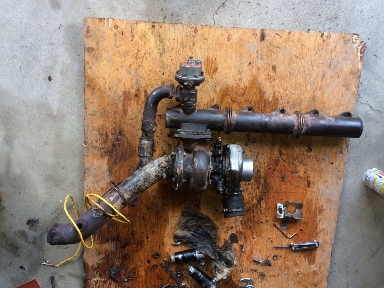
Here's the original design with Callaway manifold and piping as I received it:
Here's the remade pipes I'm currently using:
Right now I have a block off plate on the wastegate dump so I don't have a major exhaust leak and the wastegate is just venting to the engine bay.
Re: 633CSi Turbo - Not Really Callaway Anymore - 1/14/2018
I have my old TCD downpipe with the integrated recirc if you want it. 10+ years ago I had a muffler shop weld the dump tube to the downpipe because the slip fit wouldn't seal. The welds aren't super pretty but its functional and is ceramic coated. Let me know if you want it.
-
- Posts: 66
- Joined: Apr 06, 2015 9:24 PM
- Location: colorado springs
Re: 633CSi Turbo - Not Really Callaway Anymore - 1/14/2018
BRING FRANK THE WELDER BACK!! (He is the true hero of this thread)
I may have a 3 inch section of wastegate tubing you can use to lengthen your exhaust. It was a length I cut off from my screamer pipe that is just laing somewhere in my garage. I'll see if I can find it
Re: 633CSi Turbo - Not Really Callaway Anymore - 1/14/2018
Tom, is there a reason you couldn't point the compressor down (towards the ground) and run a hard 90° elbow and keep the outside outlet pipe all down below as opposed to going up over the manifold/intake pipe and back down again?
Re: 633CSi Turbo - Not Really Callaway Anymore - 1/14/2018
Yes, if you read back, Frank the welder did save this car as it wouldn't be safe to be driving without his repair work! I think he charged to much as he was a portable guy who usually made metal fences/gates and repaired heavy machinery like tractor buckets and things. I thought about using him for a cage but I am not ready to commit to something like that (still years later) and I think I ought to use a professional cage builder at that point...
With the TCD manifold, the compressor was too large to do the routing you suggest George.. .It was my original plan, but it interfered with the block with the snail having almost it's largest diameter outward in the direction of the block (The callaway manifold allowed this same turbo to fit in that orientation, however, which is how I ran it for the past few years).
Re: 633CSi Turbo - Not Really Callaway Anymore - 1/14/2018
Small update.
I took the car for a mountain drive a few weeks ago. We went up to 10,000 feet and I found that my car was running super rich below atmospheric pressures. It wasn't a huge deal as I was under load and got into boost a little bit, but even with EGO control at 10% authority I had mixtures of 13.5:1 where I should have been at 15.5:1 during cruise.
We stopped part way and restarting the car reset my baro setting. However, this introduced another problem. As I drove down the mountain, cruise became leaner and leaner. I suspected originally that this was baro correction as we were getting into more dense air.
Well I took the car for another mountain drive this weekend after adjusting baro correction to purely theoretical values and turning on my MAP daddy sensor for real time adjustment. I tuned it with autotune as I drove at 5500ft and stopped as we started to climb. Temperature was about 65F and I was able to notice that AFR's seemed relatively consistent based on the same throttle conditions as we went up to 7000 and 8000 feet. I did this with 0 EGO authority, so I suspect my baro correction is good and working.
On the return trip, I continued to autotune as we reached the flat areas. I have a slight miss it seems at low loads, even though AFR's looked good in 14-15 range in low load cruise.
Fast forward to yesterday, I start the car in 40F weather and instead of idling near 13.8, it was idling near 12:1 after Warm up enrichment shut off. I did not use EGO in this area, but if I can't consistently idle the same AFR, I have a problem. So obviously I have issues with temperature that is causing my problems. I suspected this over a year ago but am really frustrated as to what is going on.
I am starting to suspect that my injectors are too large (42# Green Giant's, authentic). I idle at pulse width of 1.3mS, and my dead time was set to .89mS. So i really don't have a large consistent pulse. Even at my max boost of 16psi, my duty cycle is only 50%. I am starting to think I should try putting in some ~30# injectors in and see what improves.
Still, how does temperature affect the mixture so much? I fixed my curve to 100% MAT correction, so I had no MAT adjustment from a few days earlier. Baro pressure really hadn't changed much. I need to look at pulse width and verify it was the same for both (I suspect it was).
I found this article and it is the only thing that makes any sort of sense. However, it doesn't explain why I am significantly richer:
Other thoughts?
I took the car for a mountain drive a few weeks ago. We went up to 10,000 feet and I found that my car was running super rich below atmospheric pressures. It wasn't a huge deal as I was under load and got into boost a little bit, but even with EGO control at 10% authority I had mixtures of 13.5:1 where I should have been at 15.5:1 during cruise.
We stopped part way and restarting the car reset my baro setting. However, this introduced another problem. As I drove down the mountain, cruise became leaner and leaner. I suspected originally that this was baro correction as we were getting into more dense air.
Well I took the car for another mountain drive this weekend after adjusting baro correction to purely theoretical values and turning on my MAP daddy sensor for real time adjustment. I tuned it with autotune as I drove at 5500ft and stopped as we started to climb. Temperature was about 65F and I was able to notice that AFR's seemed relatively consistent based on the same throttle conditions as we went up to 7000 and 8000 feet. I did this with 0 EGO authority, so I suspect my baro correction is good and working.
On the return trip, I continued to autotune as we reached the flat areas. I have a slight miss it seems at low loads, even though AFR's looked good in 14-15 range in low load cruise.
Fast forward to yesterday, I start the car in 40F weather and instead of idling near 13.8, it was idling near 12:1 after Warm up enrichment shut off. I did not use EGO in this area, but if I can't consistently idle the same AFR, I have a problem. So obviously I have issues with temperature that is causing my problems. I suspected this over a year ago but am really frustrated as to what is going on.
I am starting to suspect that my injectors are too large (42# Green Giant's, authentic). I idle at pulse width of 1.3mS, and my dead time was set to .89mS. So i really don't have a large consistent pulse. Even at my max boost of 16psi, my duty cycle is only 50%. I am starting to think I should try putting in some ~30# injectors in and see what improves.
Still, how does temperature affect the mixture so much? I fixed my curve to 100% MAT correction, so I had no MAT adjustment from a few days earlier. Baro pressure really hadn't changed much. I need to look at pulse width and verify it was the same for both (I suspect it was).
I found this article and it is the only thing that makes any sort of sense. However, it doesn't explain why I am significantly richer:
I suspect my low pulse width is just non linear or not consistent for all 6 injectors. Smaller injectors and increased pulse width/duty cycle are what I am thinking of trying next. I'm going to explore injector dead time one last time before switching injectors...Fuel Injector Heat soak
This one has taken me quite a while to narrow down. The symptom is that with a heat-soaked start, such as when I stop at the grocery store for 20 minutes, the car will idle significantly leaner.
The usual suspect is heat-soaked MAT but I found that even with MAT correction completely turned off I was still having the issue. The curious thing was that even at identical injector pulsewidths it was still idling much leaner. For instance, at normal operating temperature my idle PW is 2.2ms and will be at around 14.4 AFR. During a heat-soaked idle it will still be at 2.2ms but up around 16.0 AFR.
Why?
I started to hypothesize that the fuel injectors themselves were getting heat soaked and that the extra resistance in the copper coil windings was increasing the latency, therefore less of the 2.2ms PW was going towards delivering fuel.
I found some literature that showed injector latency can increase as much as 100ns which is .1ms.
If my idle PW is 2.2ms, that means the actual squirt is around 1.1ms with my normal 1.1ms latency. (squirt + latency = 2.2ms). If the latency is increased by .1 ms that means the squirt is reduced from 1.1ms to 1.0ms, a 10% reduction and certainly enough to explain the lean idle!
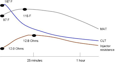
A plot of injector resistance with time after a hot shutdown.
I plotted injector resistance with time after a hot engine shutdown and found that the resistance does increase significantly. I'm guessing it's the fuel that cools the injector when the engine is running. As soon as the fuel flow stops it heats up, increases the resistance which increases latency.
I was hoping that I could correlate heat soak of the MAT with heat soak of the injector but I don't think it's good enough to use for software compensation.
For now, there's nothing that can be done to compensate for this directly. Know that it exists and is not the same as MAT heat soak. I don't use closed-loop EGO at idle because it creates more instability than it solves.
Other thoughts?
Last edited by tschultz on Mar 06, 2018 8:15 PM, edited 1 time in total.
-
- Posts: 513
- Joined: Dec 08, 2008 11:33 PM
Re: 633CSi Turbo - Not Really Callaway Anymore - 1/14/2018
I'm using 55# low z with no problems. I am at sea level, so no elevation change to deal with.
Re: 633CSi Turbo - Not Really Callaway Anymore - 1/14/2018
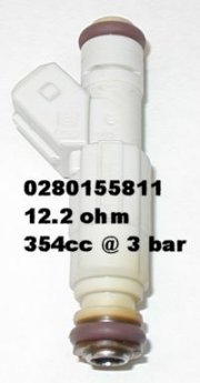
I was able to get new injectors ordered and installed over the weekend. I am stepping down from 42#'s to 34#'s (@3bar) from some sort of 3.8L GM vehicle (L67 V8 supercharged)--Bosch#: 0280 155 811
These are high impedance injectors like stock and I was trying to keep the same type.
My 1.3mS pulse width at idle changed to about 2mS and overall the car seems to run more smoothly. I have to go back through and revise my VE table, but yesterday the idle and cruise seemed smoother than before. Part of the reason I suspected the injectors as the problem was because the low speed cruise condition would give me a lean/surging feeling like the engine wasn't happy.
Well with my altitude, I have only about 83% of the air of people at sea level. So if they are close to the edge of being to big at sea level, I suspected they were actually too big for me up here.
A good article on the subject: http://www.enginelabs.com/engine-tech/t ... -with-fic/
I need to verify my injector dead times (plotting Map/AFR on X axis vs PW on Y axis. Use intercept value from the trendline of the lower pulse width range), which I believe are lower than the suggested .9mS. Hoping to mess with that tonight.
This weekend I'm also going to be looking at my downpipe and exhaust setup with a vBand clamp for easier install/removal. Updates to come.
These are high impedance injectors like stock and I was trying to keep the same type.
My 1.3mS pulse width at idle changed to about 2mS and overall the car seems to run more smoothly. I have to go back through and revise my VE table, but yesterday the idle and cruise seemed smoother than before. Part of the reason I suspected the injectors as the problem was because the low speed cruise condition would give me a lean/surging feeling like the engine wasn't happy.
Well with my altitude, I have only about 83% of the air of people at sea level. So if they are close to the edge of being to big at sea level, I suspected they were actually too big for me up here.
A good article on the subject: http://www.enginelabs.com/engine-tech/t ... -with-fic/
In my 45 minute drive yesterday, the engine seemed to run smoother in the lower load (and lower PW conditions). I am hoping to drive the car tomorrow to work to see how the tune looks with extreme temperature variations (30F morning to 70F in the afternoon) and see if my tune is more consistent.The Problem
When an engine is driven on the street, it’s exposed to extended periods of time at idle, low speeds, and low engine loads. Which means the injectors will spend more time at shorter pulse widths (shorter spray time, less fuel delivery) than if it were only driven on a race track and rarely saw any driving below six-tenths. For many years this has put plenty of enthusiasts in a battle between drivability and injector size, often opting for the smaller injectors to retain its street friendly characteristics.
“For a four-stroke engine your average fuel injector has two operating ranges – linear, from roughly 1 to 19 ms opening times [effective pulse width]; and nonlinear, 0 to 1 ms opening time,” explains Jilg. “In the linear range, the injectors will act in a very predictable manner. With smaller injectors [1,000 cc/min (95 lb/hr) and smaller], you will most likely only ever operate in this range. The nonlinear range comes into play on bigger injectors, over 1,000 cc/min, when at idle or even part throttle situations depending on the size.”
Notice how choppy the injectors’ behavior becomes as they run into the nonlinear operating range (0 to 1 ms). The bigger the injector, the more pronounced and widespread the nonlinearity becomes. The bold horizontal black lines represent the estimated fuel requirements for idle (30 cc/min) and cruise (60 cc/min).
“The nonlinear range can become very unpredictable for injector operation and fuel delivery, causing sporadic engine behavior,” continues Jilg. “The majority of the problems people have with large injectors are at idle or cruise, because you are hitting this nonlinear range and the injectors no longer match close enough in flow rate or dead time. Currently, no one offers nonlinear range matching of fuel injectors, but we are working towards implementing this into our entire line of injectors.”
I need to verify my injector dead times (plotting Map/AFR on X axis vs PW on Y axis. Use intercept value from the trendline of the lower pulse width range), which I believe are lower than the suggested .9mS. Hoping to mess with that tonight.
This weekend I'm also going to be looking at my downpipe and exhaust setup with a vBand clamp for easier install/removal. Updates to come.
Re: 633CSi Turbo - Not Really Callaway Anymore - 3/18/18 Pro
A successful day today with positive news to report.
I installed the injectors and seemed to have smoother running in general. Based on some research I plotted a datalog to get an injector deadtime curve. This is MAP/AFR plotted against PW-- basically showing total fuel vs pulse width length (time). Extrapolating a trend lines gives a y-intercept for pulse width time. This intercept is the effective opening time (dead time).
Notice how there is a distinct change in the curve above 5KPa. Most injector's don't have a linear performance throughout their range. By setting dead time to match the trendline curve on the lower end, actual fueling will be most accurate since these opening and closing times are short. If the number isn't quite correct on the upper end, the VE table can be adjusted to compensate, and pulses are longer here anyway.
This past week I was driving the car to work and home and saw immediate improvements in fueling in cold vs warm temperatures. It had to be the injectors causing my problems. So now I see fluctuations, but not as drastic as before. So this seems to be the change in air temperature causing my problems.
Since I am using Map daddy real time correction, I decided to research air density changes based on altitude. I set the barometric curve to measure values that I found online and have left those settings alone. Since temperature and pressure can both be changing at the same altitude, I have wondered if these two values ever fight each other. But at this point in time, I'm thinking that leaving it active and adjusting my MAT correction curve will get me as close as I can be.
The MAT curve is scaled down from the default, but I'm still working on it. I suspect my curve has to be scaled down more than those at seal level because my air density is lower than sea level.
I found a nice open road out east and did a test boost run. Pretty happy with intake temps and it is interesting to see the change in coolant temps. This was 3rd-4th gear and a touch into 5th at 125mph. I think I need to re-gap my spark plugs as I had some breakup at 55000rpm. I'm at .032" and plan to bring them down to .025". Still running 91 octane, but notice 130kPa, that's 6.6psi for me, whereas it would probably be about 2psi if at sea level. I'm thinking of bringing it up tot 10psi to tune with, but only ~8psi for road course duty. All of the sizing software suggests the turbo doesn't hit max efficiency until 11psi or above, but I want this rig to be reliable...
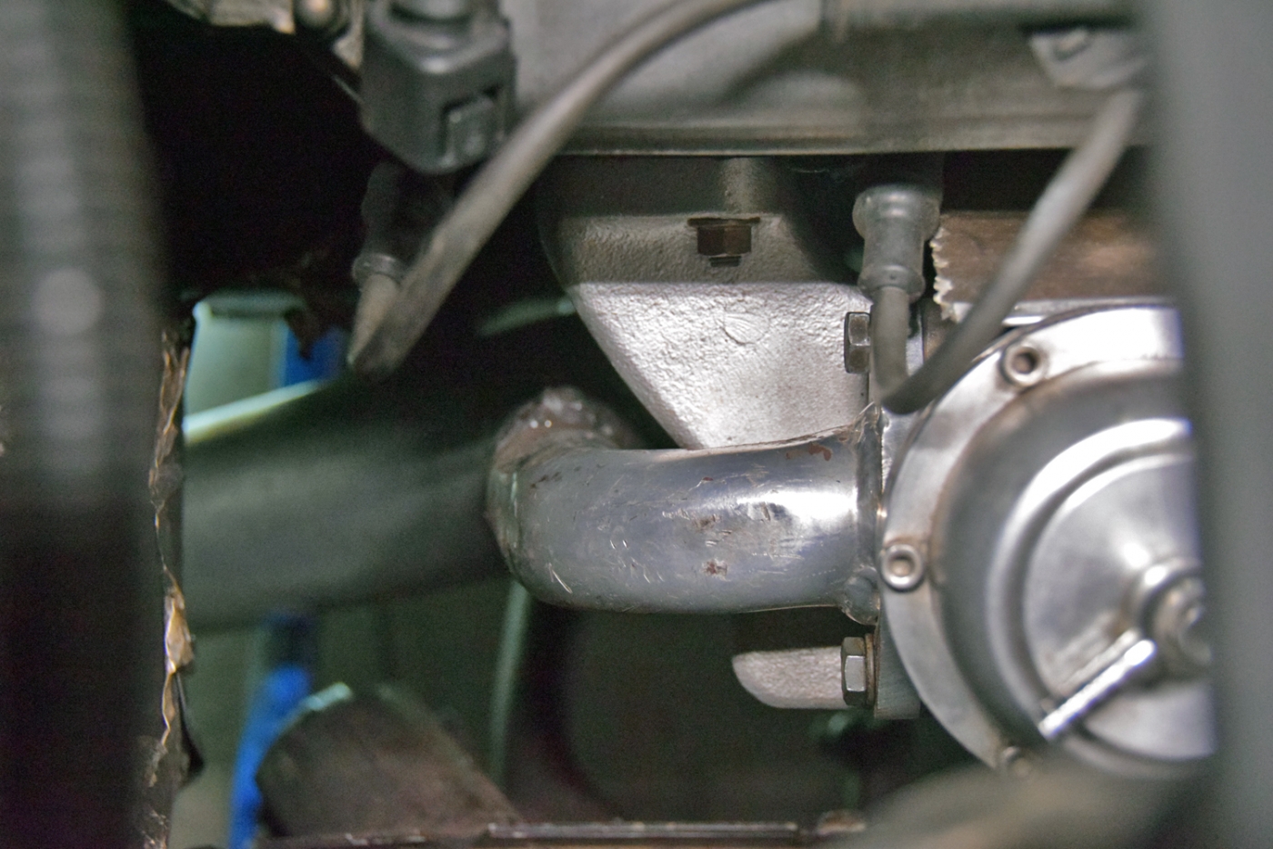
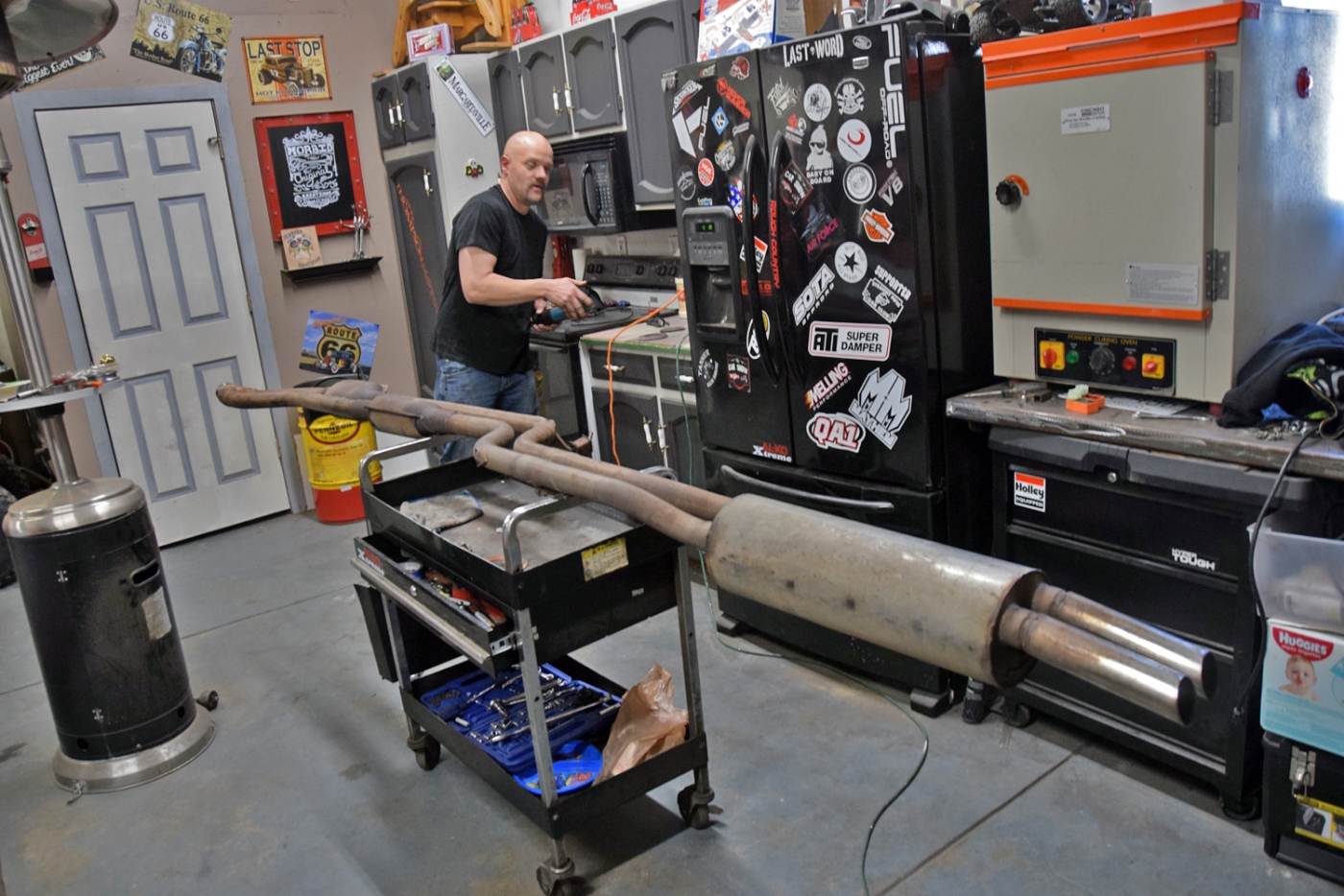
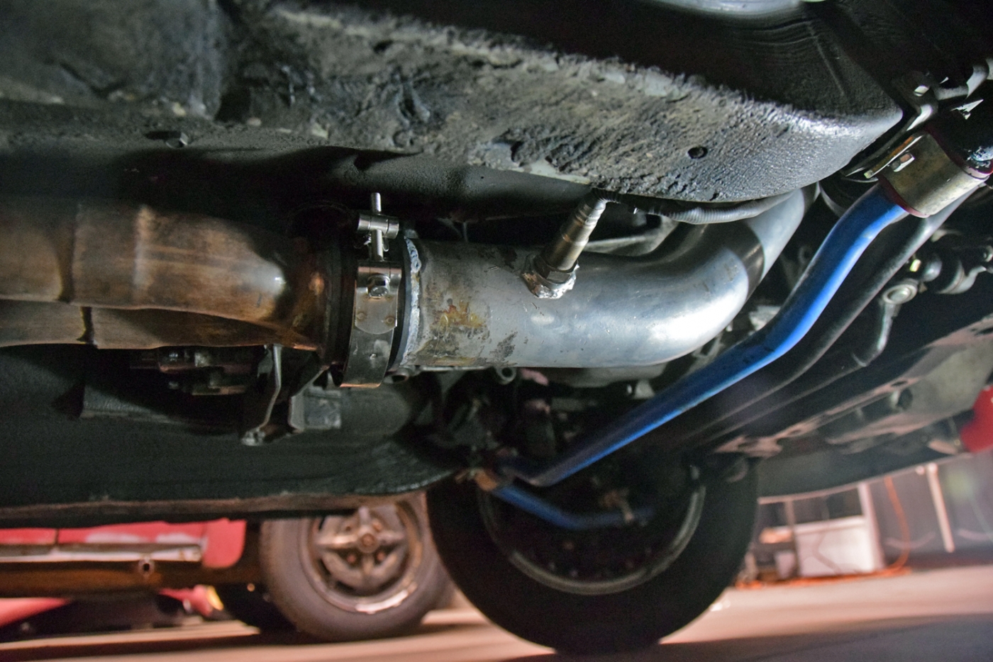
Today I was able to bring the car to a friends place to help me fix my wastegate dump and exhaust. I had never really wanted an open wastegate dump to begin with. George was nice enough to tell me he had a spare TCD turbo downpipe in his storage shed. So I decided to get it, hoping that the larger diameter and mandrel bends would further minimize back pressure post turbo. Maybe they do, maybe they don't but the main thing I wanted to fix was the exhaust connection and wastegate dump aspect. The old exhaust had a slight leak and wasn't an elegant solution. I decided that the new downpipe (ceramic coated) could likely be used and bought the vband hoping everything would fit.
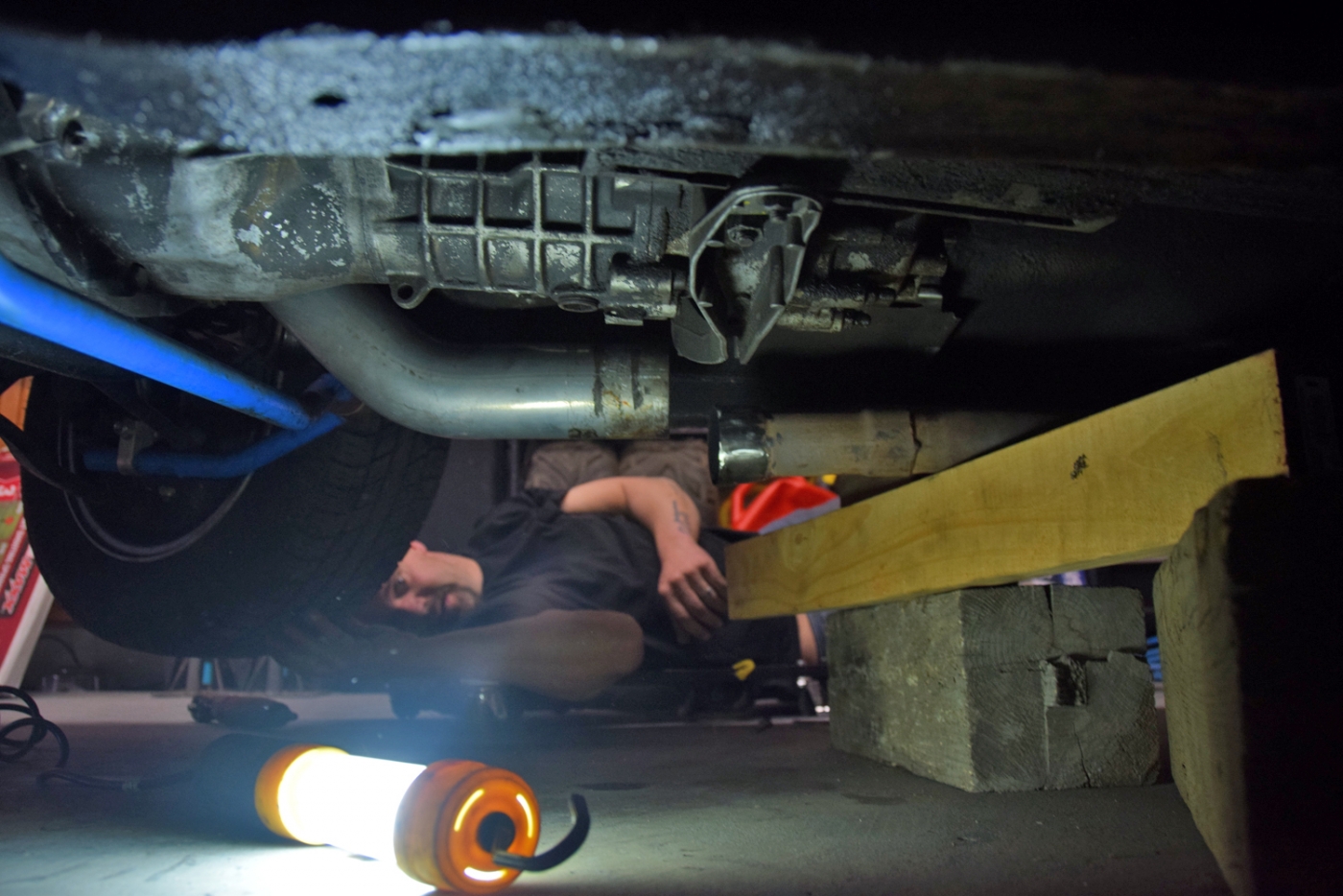
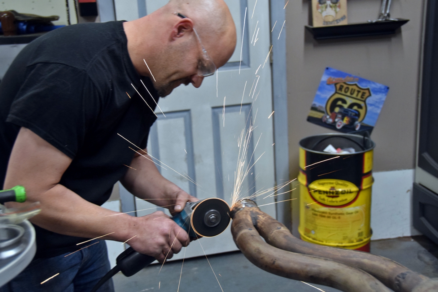
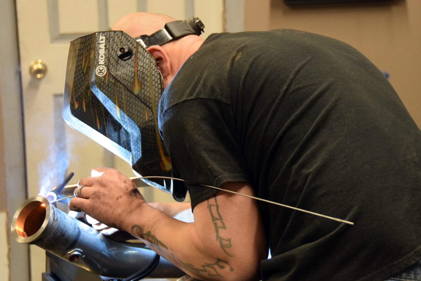
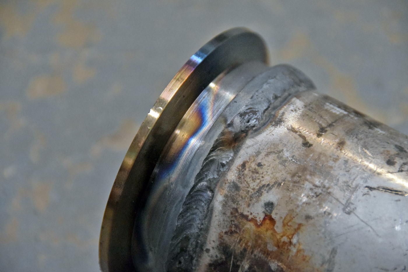
Luckily we made cuts that were close to begin with so we only pulled the parts in and out a few times. My buddy asked for some photos of the work so here's a few of him cutting and welding as well.
The workspace
Mocking up the new downpipe
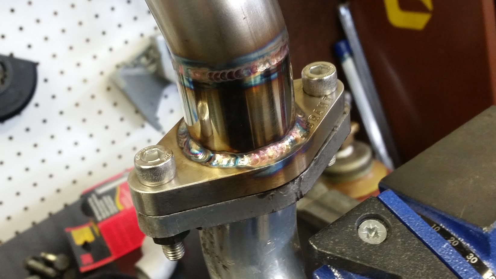
Getting the vband flange on there
TIG welds:
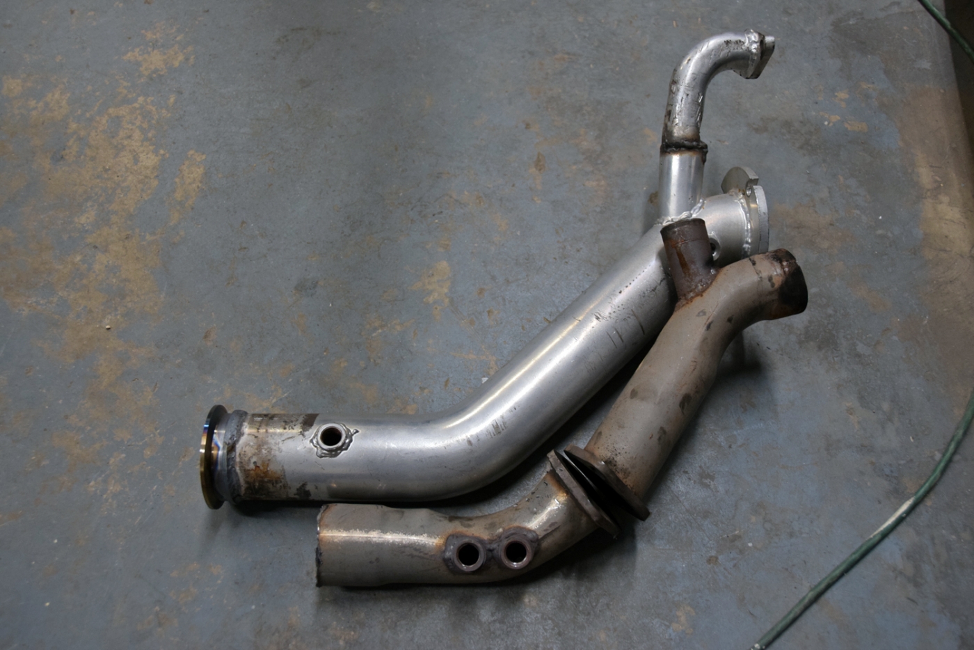
Comparison to the pipes we removed-- less sharp bends and no more bottle neck. Also I can run without a rear exhaust if I wanted and the O2/wideband sensor could still measure...:
Fitment
More tuning details to come, but the injectors have really made the difference to be able to continue tuning. The exhaust was about the last piece to the puzzle of the head gasket/turbo manifold upgrade.
Last edited by tschultz on Mar 19, 2018 9:31 AM, edited 3 times in total.